Eureka AIR delivers breakthrough ideas for toughest innovation challenges, trusted by R&D personnel around the world.

Vision-corrective Polarizing Lens

a polarizing lens and correction technology, applied in the field of polarizing lenses, can solve the problems of speeding up the poor vision decaying, and achieve the effects of simple structure, high adhesive strength, and high rate of good productiv

Inactive Publication Date: 2008-06-26
WANG WEI CHEN
View PDF0 Cites 24 Cited by
  • Summary
  • Abstract
  • Description
  • Claims
  • Application Information

AI Technical Summary

Benefits of technology

[0006]It is therefore a main object of the present invention to provide a vision-corrective polarizing lens that has simple structure, and adapts to manufacturing various optical substrate, not only guarantee optical performance, but also add polarizing function to the optical substrate.
[0014]Due to applying above-mentioned structure, the present invention substitutes the adhesive layer for the conventional adhesion agent, so that said adhesive layer can be bonded on the PC optical substrate by injection-molding to carry out bonding different objects together in bonding the polarizing film and the PC optical substrate with simple structure and high adhesive strength without blistering, separating, splitting and so on bad phenomena, in this case, the rate of good productive is kept in high level, it not only guarantees optical performance, but also adds polarizing function to the optical lens, therefore the present invention can be applied widely on manufacturing various lens, especially to the optical lens, such like near-sighted lens, far-sighted lens, presbyopia lens and gradual near-sighted lens and so on, to make these optical lens not only correct the poor vision, but also to make the visual object more clear without visual-tire happened on the eyes.

Problems solved by technology

But, the optical lens such like near-sighted lens, far-sighted lens, presbyopia lens and gradual near-sighted lens and so on, are used for correcting poor vision, as regards the poor visual eyes, the reflected light, the blazing light, the deflected light and so on are very sensitized, so these glaring lights not only are unfavorable to the vision correction, but also speed up the poor vision decaying, therefore come to the conclusion that the optical lens needs to increase polarizing function urgently for clearing visual field and avoiding eye vision-tiring.

Method used


Image

  • Vision-corrective Polarizing Lens
  • Vision-corrective Polarizing Lens
  • Vision-corrective Polarizing Lens

Examples


first embodiment

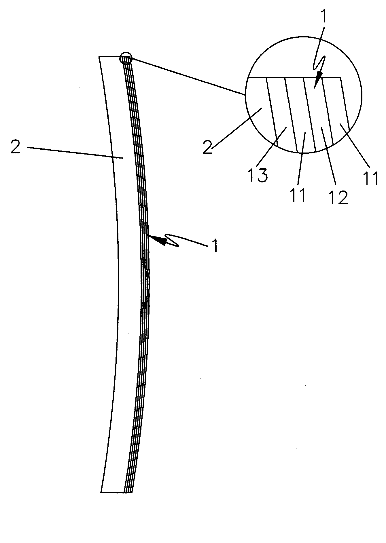
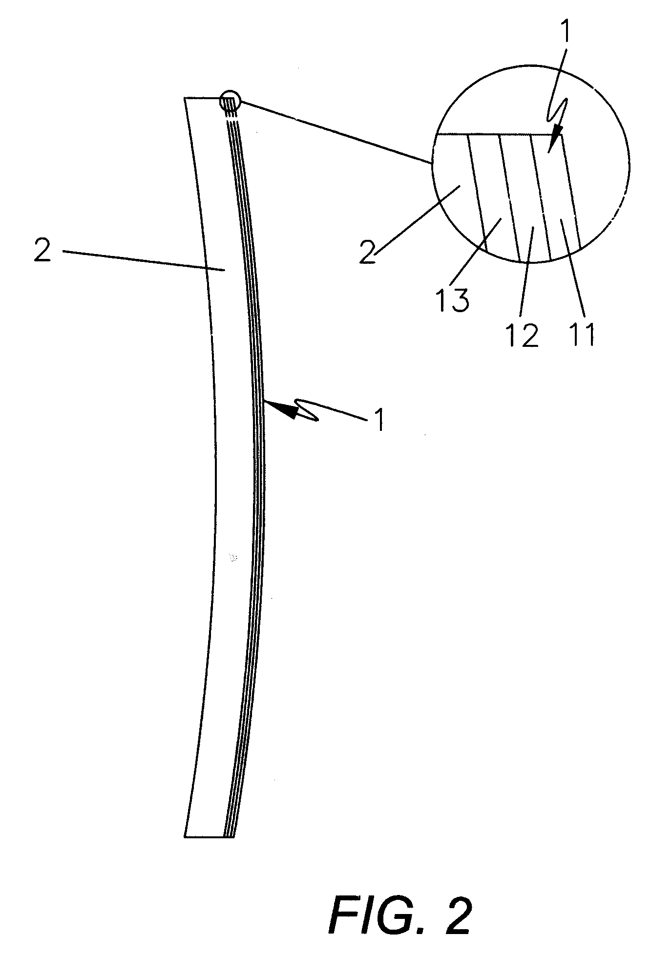
[0021]In the first embodiment, said protection layer 11 is a TAC layer, and said adhesive layer 13 is PC layer as same as the PC optical substrate, as such the PC optical lens is consisted of four layers including three-layer polarizing film 1 comprised of TAC layer, PVA base and PC layer.

second embodiment

[0022]In the second embodiment, said protection layer 11 is a PET layer, and said adhesive layer 13 is PET layer too, as such the polarizing film 1 is structured of PET layer, PVA base and PET layer, so the whole PC vision-corrective optical lens includes four layers.

third embodiment

[0023]In the third embodiment, said protection layer 11 is a PMMA layer, and said adhesive layer 13 is PMMA layer bonding on the PC optical substrate 2, as such the polarizing film 1 is structured of PMMA layer, PVA base and PMMA layer, so the whole PC vision-corrective optical lens includes four layers.

[0024]Of course, said protection layer 11 and said adhesive layer 13 also can use other either same or different materials.

[0025]Said polarizing film 1 is bonded on the PC optical substrate 2 by said adhesive layer 13 together to construct the PC vision-corrective polarizing lens.


PUM


Abstract

The present invention provides a PC vision-corrective polarizing lens consisted of a polarizing film and an optical substrate, wherein said polarizing film includes protection layer, PVA base and adhesive layer bonding on the surface of the PC optical substrate by injection-molding. The present invention with simple structure and widely adapting to near-sighted lens, far-sighted lens, presbyopia lens and gradual near-sighted lens and so on, not only corrects the poor vision, but also makes the visual object more clear under the cooperating of the polarizing function without visual-tire happened on the eyes.

Description

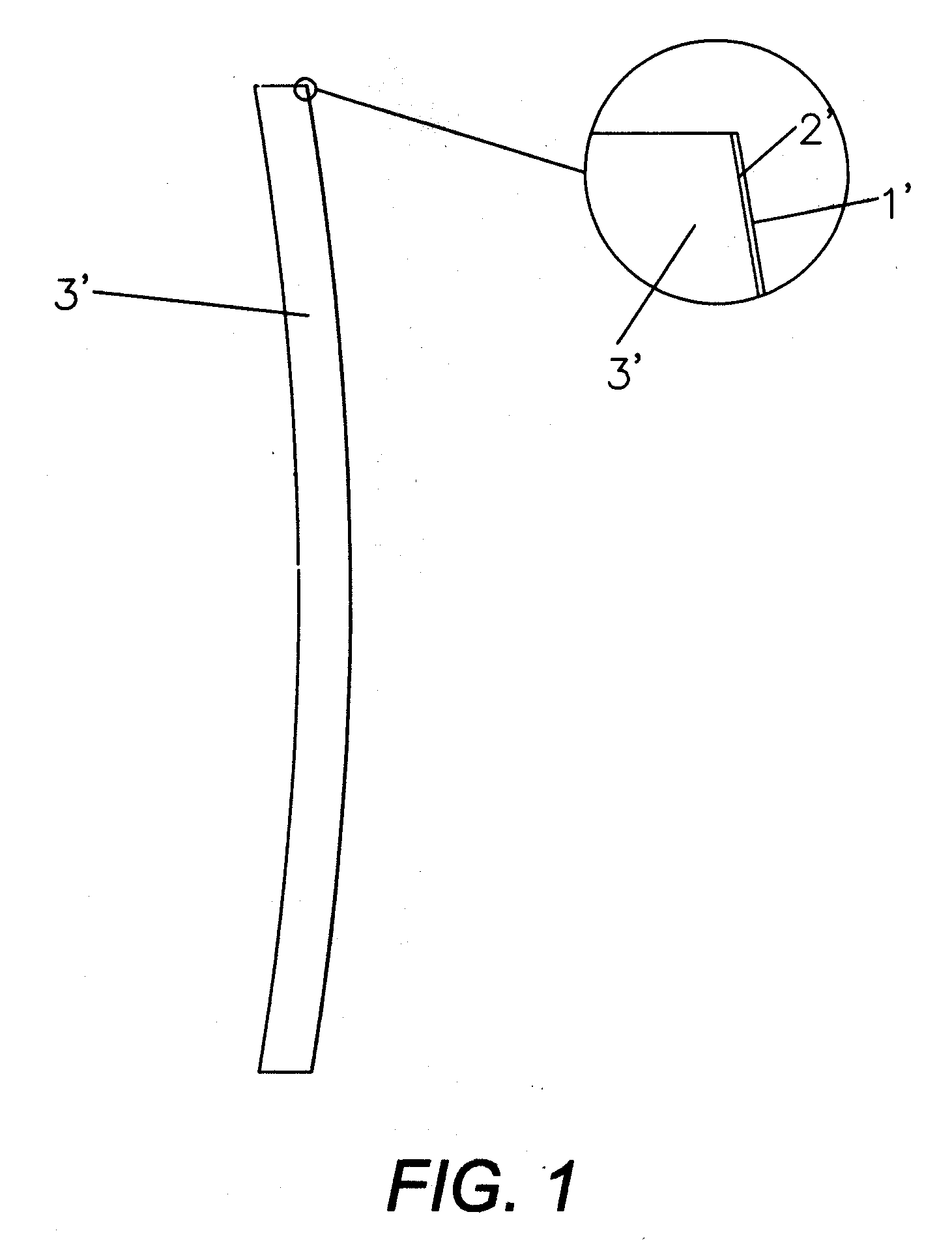
BACKGROUND OF THE INVENTION[0001]1. Field of the Invention[0002]The present invention relates to polarizing lens, and more particularly to vision-corrective polarizing lens.[0003]2. Description of Prior Art[0004]As well known, when sunlight shines on object, it is naturally deflected or reflected to generate dazzling light, human eyes can be easy to feel visual-tire under the glaring light. And polarizing lens can make all the sunlight including reflected or multi-deflected rays transmit the lens in uniform direction, so by the filter of said polarizing lens, the glaring light can be reduced in the eye sight, especially to the reflected light, the dazzling light, the deflected light and so on, and the visual distance can be extended, especially to the drivers of vehicles, a wide and clear visual field can be presented by using the polarizing lens.[0005]In accordance with the conventional polarizing lens, as shown in FIG. 1, it is typically cohered of a polarizing film 1′, adhesion a...

Claims


Application Information

Patent Timeline
IPC IPC(8): G02C7/12
CPCG02C7/12
Inventor WANG, WEI CHEN
Owner WANG WEI CHEN
Why Eureka
Eureka Blog
Learn More