Bio-flexible spinal fixation apparatus with shape memory alloy

a bio-flexible, spinal fixation technology, applied in the field of spinal fixation apparatus, can solve the problems of serious back pain, inability to take daily activities, and inability to fix the vertebra of the spine, and achieve the effect of simple connection and easy connection

Active Publication Date: 2006-03-23
PARK KYUNG WOO
View PDF15 Cites 394 Cited by
  • Summary
  • Abstract
  • Description
  • Claims
  • Application Information

AI Technical Summary

Benefits of technology

[0024] To solve the problems, a primary object of the present invention is to provide a spinal fixation apparatus which can easily and simply achieve a connection between a pedicle screw and a rod, even if it is slightly out of alignment of the pedicle screws during surgery, by deforming the shape and length of each of the rods and the transverse link which are made from a shape memory alloy of which the shape is changed at a specific temperature.
[0025] Another object of the present invention is to provide a spinal fixation apparatus which has a strength enough to correct the spine during the restoration from an elastic force so that the spinal fixation apparatus gives flexible behavior to corrected vertebral segments.
[0026] Further, another object of the present invention is to provide a staple type rod which is made from a shape memory alloy. The staple type rod of the present invention can easily and simply perform an operation of the vertebra correction and reduce the number of parts, being implanted directly into selected vertebra without a pedicle screw.
[0033] In accordance with still another aspect of the present invention, there are provided a spinal fixation apparatus comprising: at least one pedicle screw which has a head at a top portion thereof and a thread formed below the head to be implanted into a pedicle of a vertebra, wherein the head has a reception cavity and two parallel sockets formed in a bottom of the reception cavity; a pair of staple rods connected to the pedicle screws for preventing a movement of the vertebra, wherein one side of each of the rods is directly implanted into a pedicle of the vertebra and the other side is inserted into one of the sockets; and at least one set member which is inserted into the reception cavity of the head of the pedicle screws for preventing a movement of the rod.

Problems solved by technology

However, the vertebra of the spine can be injured or wrenched by external environments, abnormal postures for a long time and anaplastia and so on, which may induce a serious back pain by pressing the nerve system passing through the spine.
Patients, who have been injured in a part of his spine, cannot take their activities in daily life, because the injured part of the spine is compressed by adjacent other parts of the spine.
It is very difficult to keep the line of his lumber normal since the vertebra segment is fused together with the rod to correct the vertebra bodies.
In particular, it has some problems in that the rod can be broken and buried in the vertebra, when a shock is inflicted upon the lumbar vertebra.
That causes the difficulty of standardizing each single products and making various shapes, thereby increasing the cost of products.
Therefore, if the pedicle screws are not fixed uniformly between the segments, it was very difficult to install the straight rod on the pedicle screws.
The operating work using the conventional vertebra fixation apparatus needs accuracy, because he must correctly grasp the location to install the pedicle screw and then have to make a hole in vertebra with a burden on the surgeon.
Also, it takes a lot of times to make the rod based on a curved shape of patient's vertebra and to set the location of pedicle screw.
However, the rod structure results in a lose of the basic function of the spine correction since the elastic connection portion causes large movement.
Therefore, the secure connection between the spinal segments is not achieved.
Also, when the pedicle screws are out of the straight line, the rod structure has a problem in that it is difficult to connect the rod to the pedicle screw.
This problem in the transverse link 400 requires to take a long time for an operation on the surgery.
In case where it is difficult to assemble the transverse link 400, it may be omitted; however, this will cause a defect of the surgery.

Method used


Image

  • Bio-flexible spinal fixation apparatus with shape memory alloy
  • Bio-flexible spinal fixation apparatus with shape memory alloy
  • Bio-flexible spinal fixation apparatus with shape memory alloy

Examples


first embodiment

[0068] A first embodiment will be described in detail referring to FIGS. 5 to 14.

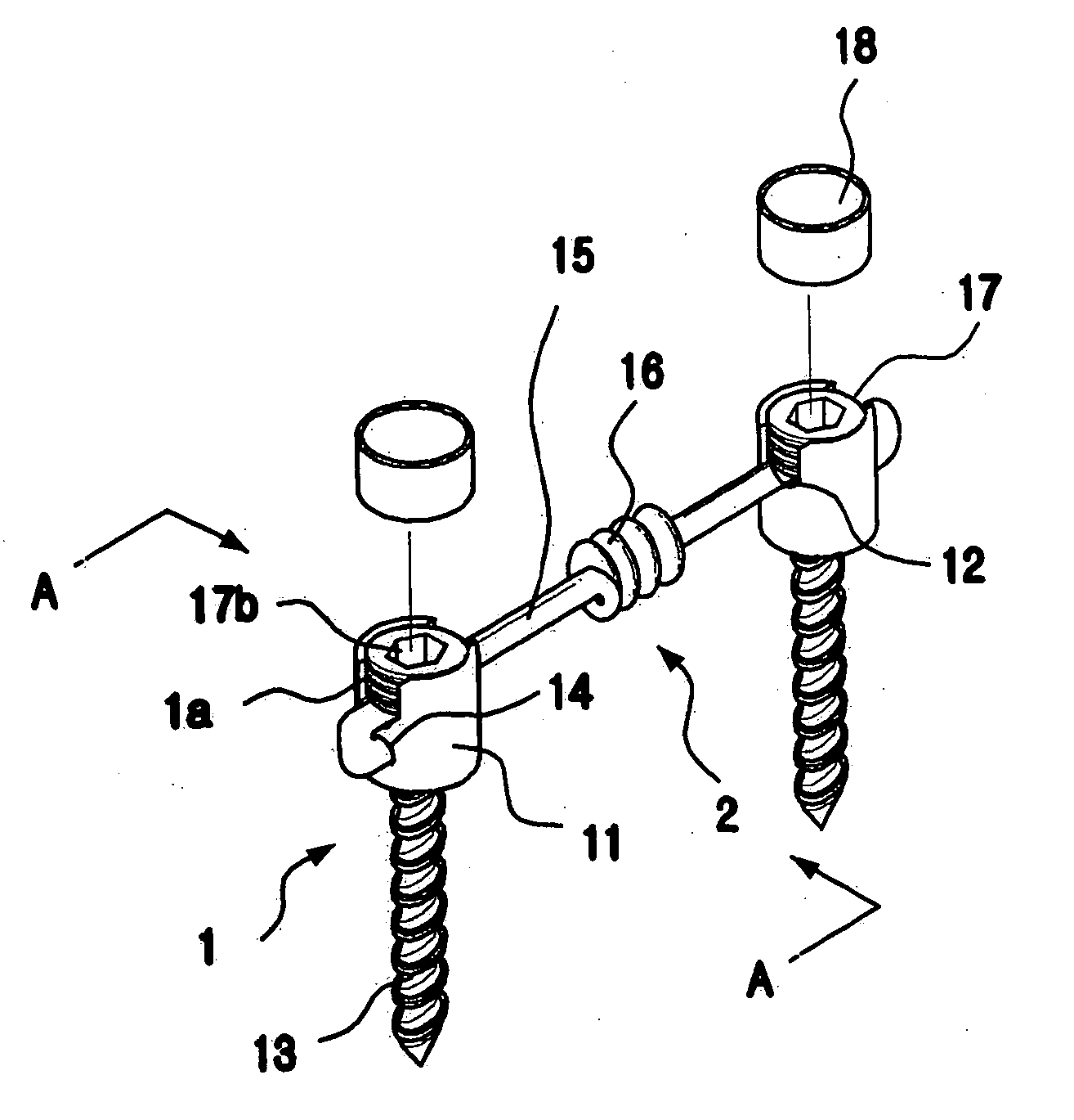
[0069] According to the first embodiment of present invention, the spinal fixation apparatus includes a plurality of pedicle screws 1 implanted into the patient's vertebra; a pair of rods 2 located in both laterals of the spine and connected to the pedicle screws for preventing a movement of the vertebra; and a number of transverse links 3 for providing space between the rods.

[0070] Referring now to FIGS. 5 to 7, the pedicle screw 1 comprises a head 11 formed at a top portion thereof and a thread 13 formed below the head to be implanted into the vertebra. The head 1 has a reception cavity 11a to receive the rod 2 and at least one rod groove 12 at the bottom of the reception cavity 11a. A diameter of the rod groove 12 corresponds to that of the rod 2.

[0071] The rod 2 has a rod body 15 which is bent and then has a hook shape at both ends thereof and the rod 2 has an elasticity section 16 formed in the m...

second embodiment

[0098] In the second embodiment, the head 11 of the pedicle screw 1 is formed with a pair of first rod grooves 21 and 21′ to locate the rod 2 on an upper portion thereof. Also, a pair of rod inserting recesses 22 and 22′ are respectively formed below the rod grooves 21 and 21′ and the rod inserting recesses 22 and 22′ are positioned in the same axis of the rod grooves 21 and 21′, respectively. A female thread 23 is formed on an inner surface of the head 11 at a predetermined depth.

[0099] A head cap 20 is provided on the upper portion of the head 11 and the head cap 20 has a pair of second rod grooves 24 and 24′ corresponding the first rod grooves 21 and 21′. A fixing screw 25 is joined to the female thread 23 passing through the head cap 20 so that the head 11 is strongly fixed to the head cap 20.

[0100] A diameter of the first rod grooves 21 and 21′ and the second rod grooves 24 and 24′ is correspondent to that of the rods 2 and 2′. And the rod inserting grooves 22, 22′ have the sa...

third embodiment

[0104] the present invention will be described in detail referring to FIGS. 16 and 17.

[0105] A plurality of pedicle screws 40 according to this embodiment comprises; a head formed at a top portion thereof, wherein the head has a reception cavity 41a and two parallel rod grooves 42 and 42′ in bottom surface of the reception cavity 41a; and a thread 43 formed below the head to be implanted into a pedicle of the vertebra.

[0106] Two parallel rod grooves 42 and 42′ in the reception cavity 41a contributes to a connection of the rods 50 and the pedicle screws 40 without an additional connector. Here, the rod grooves 42, 42′ have a diameter equivalent to the rod 50.

[0107] A set screw 44 is inserted into the reception cavity 41a of the head 41 of the pedicle screws 40 for preventing a movement of the rod 50. In order to securely tighten the rod 50, the set screw 44 has an outer thread 44a and a recess 44b which has a hexagonal cross-section view in the reception cavity 41a of the head 41. ...


PUM


Abstract

The present invention relates to a spinal fixation apparatus having a segment flexible rod for connecting pedicle screws and a transverse link for spacing out the rods, which are made from a shape memory alloy, thereby easily and simply connecting the rods and the pedicle screws. According to the present invention, it can easily and simply fit the rods to the misaligned pedicle screw, even if it may be a failure of alignment of the pedicle screws in surgery. Also, it can easily set up the transverse link on a pair of the longitudinal rods, even if the longitudinal rods are declined or are not in parallel.

Description

BACKGROUND OF THE INVENTION [0001] 1. Field of the Invention [0002] The present invention relates to a spinal fixation apparatus which can correct and immobilize injured or deformed human spine; and, more particularly, to a spine fixation apparatus for easily carrying out an operation on the spine, by using segment flexible rods and a transverse link which are made from a shape memory alloy, so that the rod and the transverse link can elongate in different shapes with flexibility. [0003] 2. Description of the Related Art [0004] Typically, the vertebra typically consists of 24 bones (except for sacral vertebra). They are connected to each other through joint segments and there are discs between the joint segments. By this structure, the vertebra has man's posture kept and a shock absorbed. Also, the vertebra is essential to exercises and protects all internal organs from an external shock. However, the vertebra of the spine can be injured or wrenched by external environments, abnorma...

Claims


Application Information

Patent Timeline
Patent Type & Authority Applications(United States)
IPC IPC(8): A61F2/30
CPCA61B17/7004A61B17/7005A61B17/7007A61B17/7008A61B17/7011A61B2017/0645A61B17/7028A61B17/7032A61B17/7052A61B2017/00867A61B17/7026
Inventor PARK, KYUNG-WOO
Owner PARK KYUNG WOO
Why Eureka
Try Eureka