Eureka AIR delivers breakthrough ideas for toughest innovation challenges, trusted by R&D personnel around the world.

Geo-locating load balancing

a load balancing and geo-location technology, applied in the field of load balancing, can solve the problems of limited round-robin dns and flow-based load balancing, scalability issues, and failure to ensure that traffic continues

Inactive Publication Date: 2006-03-23
LEVEL 3 COMM LLC
View PDF51 Cites 354 Cited by
  • Summary
  • Abstract
  • Description
  • Claims
  • Application Information

AI Technical Summary

Benefits of technology

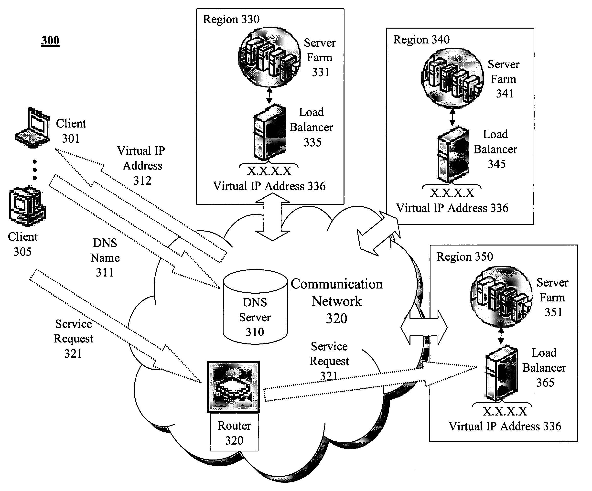
The patent describes a method and apparatus for geo-locating load balancing, which involves advertising a shared virtual IP address for multiple load balancers. The load balancers service requests from multiple servers by directing client requests to a particular server based on load balancing routines. The system includes multiple servers, load balancers, and geographically dispersed communication devices that communicate with the load balancers. The invention allows for efficient load balancing and improved performance of Voice over IP calls.

Problems solved by technology

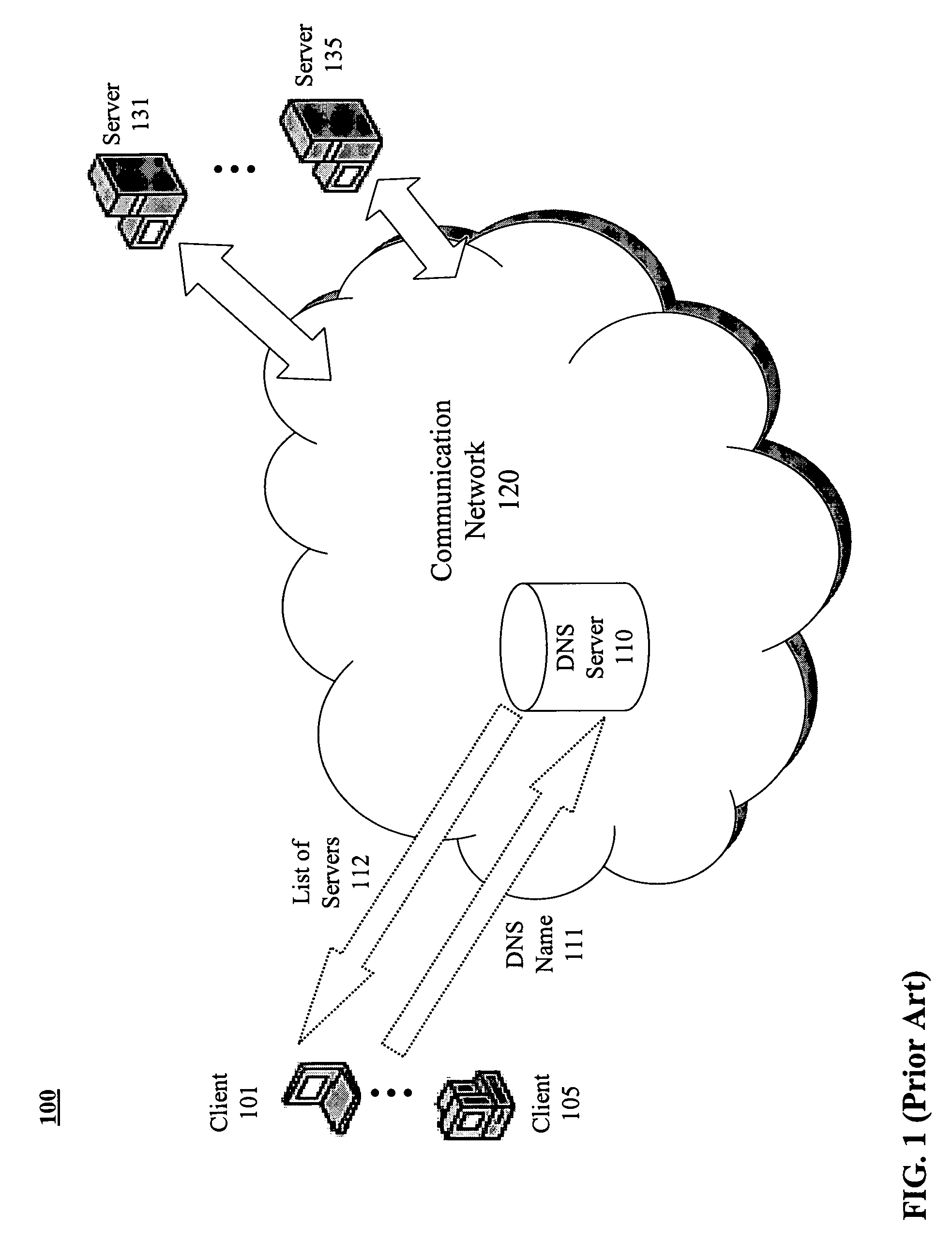
Round-robin DNS and flow-based load balancing are limited in that they do not factor into the load balancing the location of the client or the host.
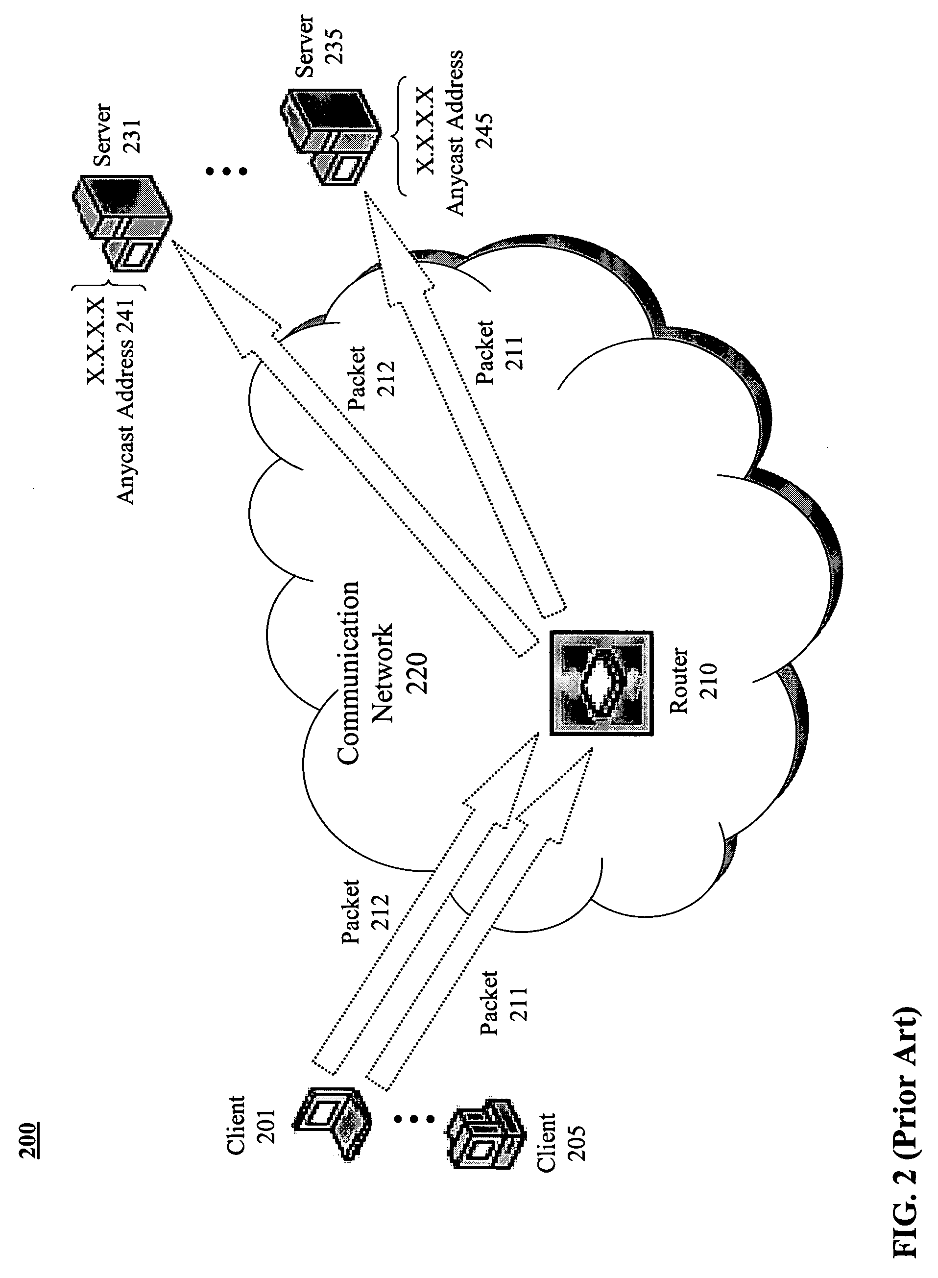
Meanwhile, Anycast addressing balances only based on network metrics, has scalability issues, and does not ensure that traffic continues to reach the same destination from message to subsequent message.
Furthermore, Anycast addressing will not scale beyond the point where the nearest server is incapable of handling all traffic in its area.
While the load balancing approaches discussed above may be adequate for web traffic and flow-based network communications, they do not address the needs of session-based, latency dependent applications, such as Voice over IP (VoiP), which aspire to reliably minimize latency through the network.

Method used


Image

  • Geo-locating load balancing
  • Geo-locating load balancing
  • Geo-locating load balancing

Examples


Embodiment Construction

[0025] Methods and apparatus are described for geo-locating load balancing. Broadly stated, embodiments of the present invention seek to provide a mechanism for directing geographically dispersed clients to the “closest” feature servers without previously determining their locations and then balancing the load across the closest feature servers. According to one embodiment, a method is provided for establishing a session for a Voice over IP (VoIP) call. A voice client coupled to a communication network issues a Session Initiation Protocol (SIP) Register message to an Anycast address serviced by multiple proxy servers coupled to the communication network. The SIP Register message is received by the proxy server determined to be closest to the voice client based on metrics associated with the communication network. The closest proxy server then causes the SIP Register message to be directed to a particular registrar server of multiple registrar servers associated with the proxy server...


PUM


Abstract

Methods and apparatus are provided for geo-locating load balancing. According to one embodiment, a communication network architecture includes multiple servers, multiple load balancers, and multiple geographically dispersed communication devices. The servers provide services to the communication devices within the communication network. The load balancers each service a shared virtual Internet Protocol (IP) address common to all of the load balancers and perform load balancing of service requests on behalf of two or more of the servers that are located geographically proximate to the load balancer. The communication devices are communicatively coupled with the load balancers and are configured to issue service requests intended for any of the servers to the shared virtual IP address, whereby, upon issuing a service request, a communication device is directed to a particular server selected by a load balancing routine that is associated with a load balancer that is closest to the communication device.

Description

[0001] This application is a continuation-in-part of prior application Ser. No. 11 / 027,275, which claims the benefit of Provisional Application No. 60 / 567,542, filed May 3, 2004, and which is related to U.S. patent application Ser. No. 11 / 027,564 (Attorney Docket No. 74120-310340) entitled “Registration Redirect Server”, and filed by Terpstra on Dec. 31, 2004. Further, the entirety of each of the aforementioned applications is incorporated herein by reference for all purposes.COPYRIGHT NOTICE [0002] Contained herein is material that is subject to copyright protection. The copyright owner has no objection to the facsimile reproduction of the patent disclosure by any person as it appears in the Patent and Trademark Office patent files or records, but otherwise reserves all rights to the copyright whatsoever. Copyright© 2004 Level 3 Communications, Inc. BACKGROUND [0003] 1. Field [0004] Embodiments of the present invention generally relate to the field of load balancing. More particula...

Claims


Application Information

Patent Timeline
Patent Type & Authority Applications(United States)
IPC IPC(8): G06F15/173
CPCH04L29/12066H04L29/12783H04L61/1511H04L61/35H04L67/1002H04L67/101H04L67/1021H04L67/18H04L67/1008H04L61/4511H04L67/1001H04L67/52
Inventor SIRKIN, CRAIG
Owner LEVEL 3 COMM LLC
Why Eureka
Eureka Blog
Learn More