Connection structure of oil passage

a technology of oil passages and connecting structures, which is applied in the direction of fluid pressure sealing joints, mechanical devices, sealing details, etc., can solve the problems of increasing the adverse influence of oil leakag

Inactive Publication Date: 2006-03-30
JATCO LTD
View PDF4 Cites 4 Cited by
  • Summary
  • Abstract
  • Description
  • Claims
  • Application Information

AI Technical Summary

Benefits of technology

[0011] From the foregoing problems, it is an object of the present invention to provide a connection structure of oil passages, which can easily detect absence of an O-ring therein.

Problems solved by technology

In a case the member oil passage 51 is a discharge oil passage from the oil pump, high-pressure oil flows therein, which therefore, results in an increase in an adverse influence of the oil leakage.

Method used


Image

  • Connection structure of oil passage
  • Connection structure of oil passage
  • Connection structure of oil passage

Examples


Embodiment Construction

[0023] An embodiment of the present invention will be described with reference to the drawings.

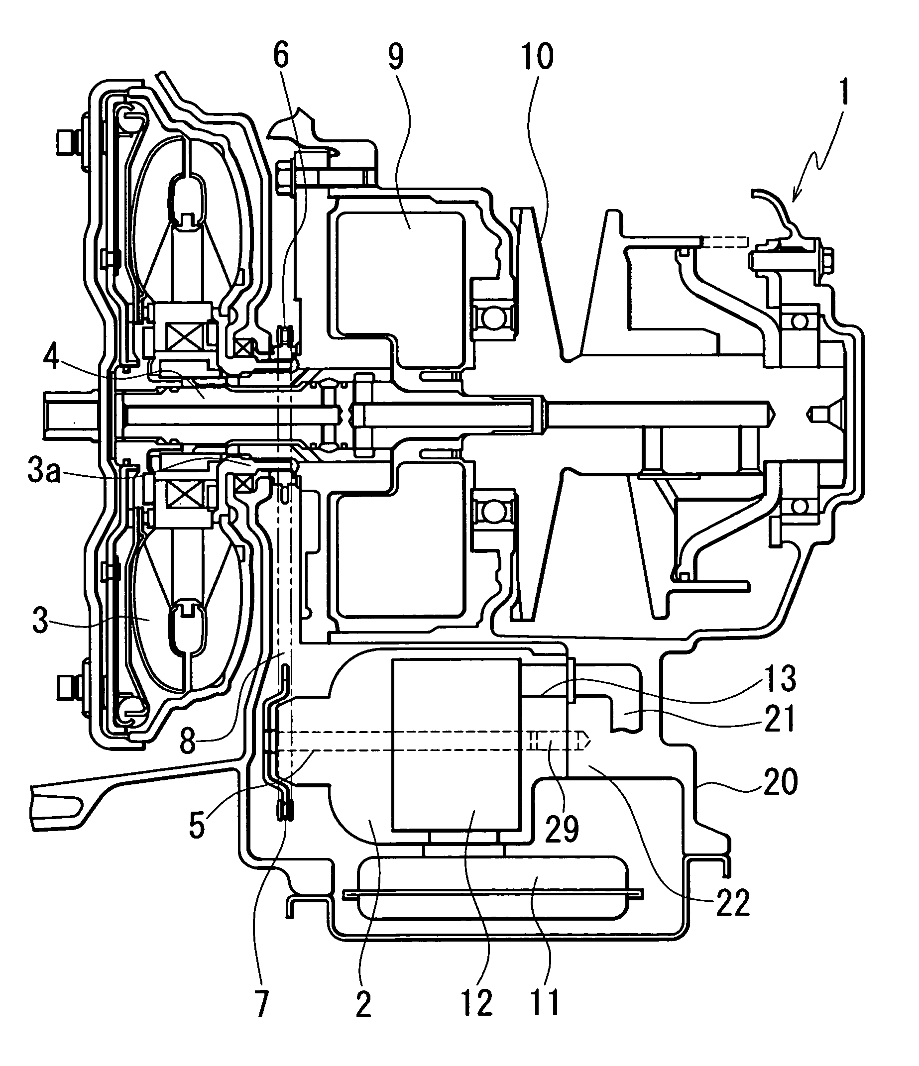
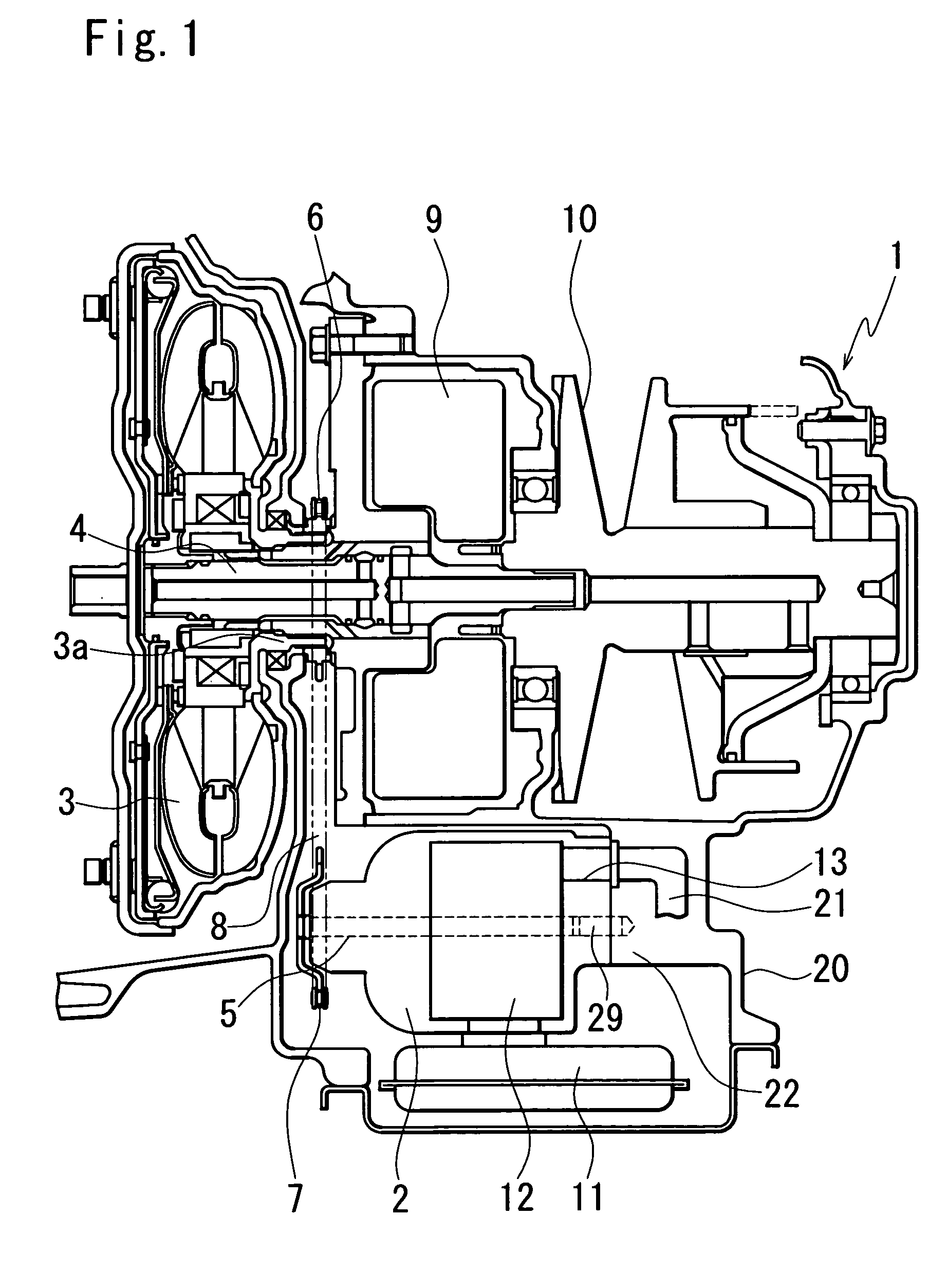
[0024]FIG. 1 is a cross-sectional view showing a periphery of an oil pump in a continuously variable transmission.

[0025] A continuously variable transmission 1 to which power from an engine is inputted is provided with an input shaft 4 to which the power from the engine is inputted through a torque converter 3, a forward / reverse switching mechanism part 9 to switch a rotation direction of the power which is inputted to the input shaft 4 and a transmission mechanism part 10 which converts a rotation speed of the input shaft 4 and transmits the converted rotation to drive wheels of a vehicle (not shown).

[0026] Further, an oil pump 2 driven by a rotational force of a sleeve 3a which is disposed coaxially with the input shaft 4 and connected to an impeller of the torque converter 3 is arranged in such a way that an oil pump rotation shaft 5 is in parallel to the input shaft 4.

[0027] Betwee...


PUM


Abstract

A large diameter part is formed in a case-side oil passage, an O-ring is fitted into the large diameter part, and an oil pump is installed to the transmission case by adjusting a discharge hole thereof and the case-side oil passage in alignment with each other. A notch is formed in radial direction from an inner peripheral surface of the large diameter part to an outer peripheral surface of a seat part. When the discharge hole and the case-side oil passage are communicated without the O-ring in the large diameter part, an oil passing through the discharge hole leaks from the notch. Thus in a state the O-ring is not assembled, an oil pressure is not increased by positively leaking the oil through the notch, whereby it can be easily detected that the O-ring is not assembled by mistake.

Description

BACKGROUND OF THE INVENTION [0001] 1. Field of the Invention [0002] The present invention relates to a connection structure of oil passages, for instance, in an automatic transmission. [0003] 2. Description of the Prior Arts [0004] Conventionally, as shown in FIG. 5, when a case-side oil passage 61 provided in a case 60 of an automatic transmission and a member oil passage 51 provided in a member 50 connected to the case 60 are communicated with each other to form a hydraulic circuit, a large diameter part 62 a diameter of which is larger than a bore diameter of the member oil passage 51 is formed in an opening of the case-side oil passage 61. An elastically deformable O-ring 70 is fitted into the large diameter part 62, and the member 50 and the case 60 are fixed each other with opposing positions of the member oil passage 51 and the case-side oil passage 61 be adjusted. [0005] In addition, the O-ring 70 is inserted between the member 50 and the case 60, thus preventing oil leakage...

Claims


Application Information

Patent Timeline
Patent Type & Authority Applications(United States)
IPC IPC(8): F16H57/04F16H57/02F16L17/06
CPCF16H57/0421F16H61/00F16H57/0489
Inventor MATSUBARA, KENJITAGUCHI, HIROMIKUNII, YASUHIKOAMANO, KATSUTOSHINISHIYAMA, HIROYUKI
Owner JATCO LTD
Why Eureka
Try Eureka