Warm or hot standby track card module for use on a wayside of a railway system

a technology of track card and standby, which is applied in the field of track card, can solve the problems of system failure in a safe manner, relay de-energized, and susceptible to lightning and other sources of over-voltag

Active Publication Date: 2018-09-20
SIEMENS MOBILITY INC
View PDF8 Cites 2 Cited by
  • Summary
  • Abstract
  • Description
  • Claims
  • Application Information

AI Technical Summary

Benefits of technology

[0006]Briefly described, aspects of the present invention relate to a track card that supports the selective redundancy concept of a railway system such that two track cards may be connected to the same track. It is understood that the inactive card will need to be insulated from the rails by means of an air-gap (relay). The inactive card will continually run online checks to verify that it is ready to take over control should the active card fails. The reception of established track codes will likely get lost for a brief moment (about 6 seconds in case of Electrcode®) but will pick up automatically afterwards. This is a warm-standby or a hot-standby concept.
[0007]In accordance with one illustrative embodiment of the present invention, a coded track circuit of a signaling control equipment to be located at a wayside location of a railway track is provided. The coded track circuit comprises a first track circuit card coupled to rails of the railway track to detect an absence of a train on the railway track, inform signallers and control relevant signals via track codes. The coded track circuit further comprises a second track circuit card coupled to rails of the railway track, the second track circuit card is inactive but ready to provide a warm-standby such that the second track circuit card to take over control from the first track circuit card should the first track circuit card fails.
[0008]In accordance with another illustrative embodiment of the present invention, a track circuit system for use at a wayside location of a railway track is provided. The track circuit system comprises a coded track circuit, a first track circuit card and a second track circuit card. The first track circuit card is coupled to rails of the railway track and coupled to the coded track circuit to detect an absence of a train on the railway track, inform signallers and control relevant signals via track codes. The second track circuit card is coupled to rails of the railway track and coupled to the coded track circuit to provide a warm-standby such that the second track circuit card to take over control from the first track circuit card should the first track circuit card fail.
[0009]In accordance with another illustrative embodiment of the present invention, a method of signaling control at a wayside location of a railway track is provided. The method comprises providing a coded track circuit, providing a first track circuit card coupled to rails of the railway track and coupled to the coded track circuit to detect an absence of a train on the railway track, inform signallers and control relevant signals via track codes and providing a second track circuit card coupled to rails of the railway track and coupled to the coded track circuit to provide a warm-standby such that the second track circuit card to take over control from the first track circuit card should the first track circuit card fail.

Problems solved by technology

If the circuit is broken, the system fails in a safe manner.
A broken rail or a failed power source causes the relay to become de-energized and report the section of track as occupied.
Track circuit cards are connected directly to the rails of a railway track and therefore are susceptible to lightning and other sources for over-voltage.
This creates a single point of failure for the signaling control equipment in a wayside location.
Current implementations of coded track circuit cards (Electrcode® or MIKROTRAX® compatible) do not support any standby concepts.

Method used


Image

  • Warm or hot standby track card module for use on a wayside of a railway system
  • Warm or hot standby track card module for use on a wayside of a railway system
  • Warm or hot standby track card module for use on a wayside of a railway system

Examples


Embodiment Construction

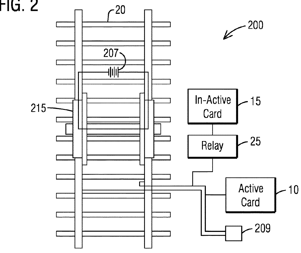
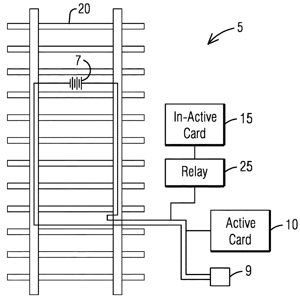
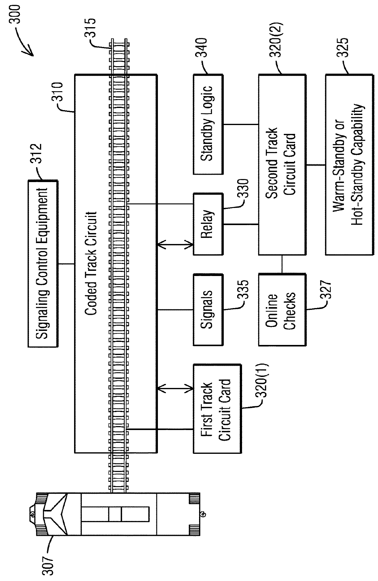
[0016]To facilitate an understanding of embodiments, principles, and features of the present invention, they are explained hereinafter with reference to implementation in illustrative embodiments. In particular, they are described in the context of being a warm-standby or hot-standby track circuit module. For example, the warm-standby or hot-standby track circuit module provides a selective redundancy as two track cards are connected to a same track on a wayside of a railway system. Warm-standby is a method of redundancy in which the secondary (i.e., backup) system runs in the background of the primary system. Data is mirrored to the secondary server at regular intervals. Hot-standby is a method of redundancy in which the primary and secondary (i.e., backup) systems run simultaneously. The data is mirrored to the secondary server in real time so that both systems contain identical information. Embodiments of the present invention, however, are not limited to use in the described dev...


PUM


Abstract

A coded track circuit of a signaling control equipment to be located at a wayside location of a railway track is provided. The coded track circuit comprises a first track circuit card coupled to rails of the railway track to detect an absence of a train on the railway track, inform signallers and control relevant signals via track codes. The coded track circuit further comprises a second track circuit card coupled to rails of the railway track, the second track circuit card is inactive but ready to provide a warm-standby or a hot-standby such that the second track circuit card to take over control from the first track circuit card should the first track circuit card fails.

Description

BACKGROUND1. Field[0001]Aspects of the present invention generally relate to signaling control at a wayside location of a railway track and more specifically relate to a track card that supports a selective redundancy as two track cards are connected to a same track on a wayside of a railway system.2. Description of the Related Art[0002]Most railroads use track circuits to determine which sections of a railway track are occupied by trains. Track circuits work by running a circuit using the rails to connect a power source at one end of the block with a relay at the far end. The relay and power source are connected to each rail by cables. As long as the circuit is complete, low voltage power flows down one rail, through a relay, and returns to the power source via the other rail. If the circuit is complete, the relay will be energized, which keeps signals in the “clear” position. If the circuit is broken, the system fails in a safe manner. A broken rail or a failed power source causes...

Claims


Application Information

Patent Timeline
Patent Type & Authority Applications(United States)
IPC IPC(8): B61L1/18B61L25/02
CPCB61L25/02B61L1/181B61L1/188B61L27/33
Inventor SCHMIDT, HOLGERHOGAN, BRIAN JOSEPH
Owner SIEMENS MOBILITY INC
Why Eureka
Try Eureka