Injector unit for the injection of fuel, and method for the operation of an injector unit of this type

Pending Publication Date: 2022-06-16
LIEBHERR COMPONENTS DEGGENDORF GMBH
View PDF0 Cites 0 Cited by
  • Summary
  • Abstract
  • Description
  • Claims
  • Application Information

AI Technical Summary

Benefits of technology

[0021]The control signal that controls the magnetic attraction of the armature element controls can thus only drop greatly for a brief moment and can again move to or close to the starting level shortly afterward. This brief decline of the control signal has the effect that the armature is moved away from the passage opening despite the brief decline of the constant signal. In this respect, the brief drop of the control signal can be dimensioned such that no temporary approach of the armature element in the direction of the passage opening occurs after

Problems solved by technology

Due to the high injection pressures of up to 2500 bar, it is not possible to control or to move the jet needle directly with the aid of a magnetic valve.
The required forces for opening and closing the jet needle would be too great here so that such a process would only be able to be implemented with the aid of very large electromagnets.
Such a design is, however, excluded due to the only limited available installation space in an engine.
It is problematic with the above-described process for releasing the passage opening that the

Method used


Image

  • Injector unit for the injection of fuel, and method for the operation of an injector unit of this type

Examples


Example

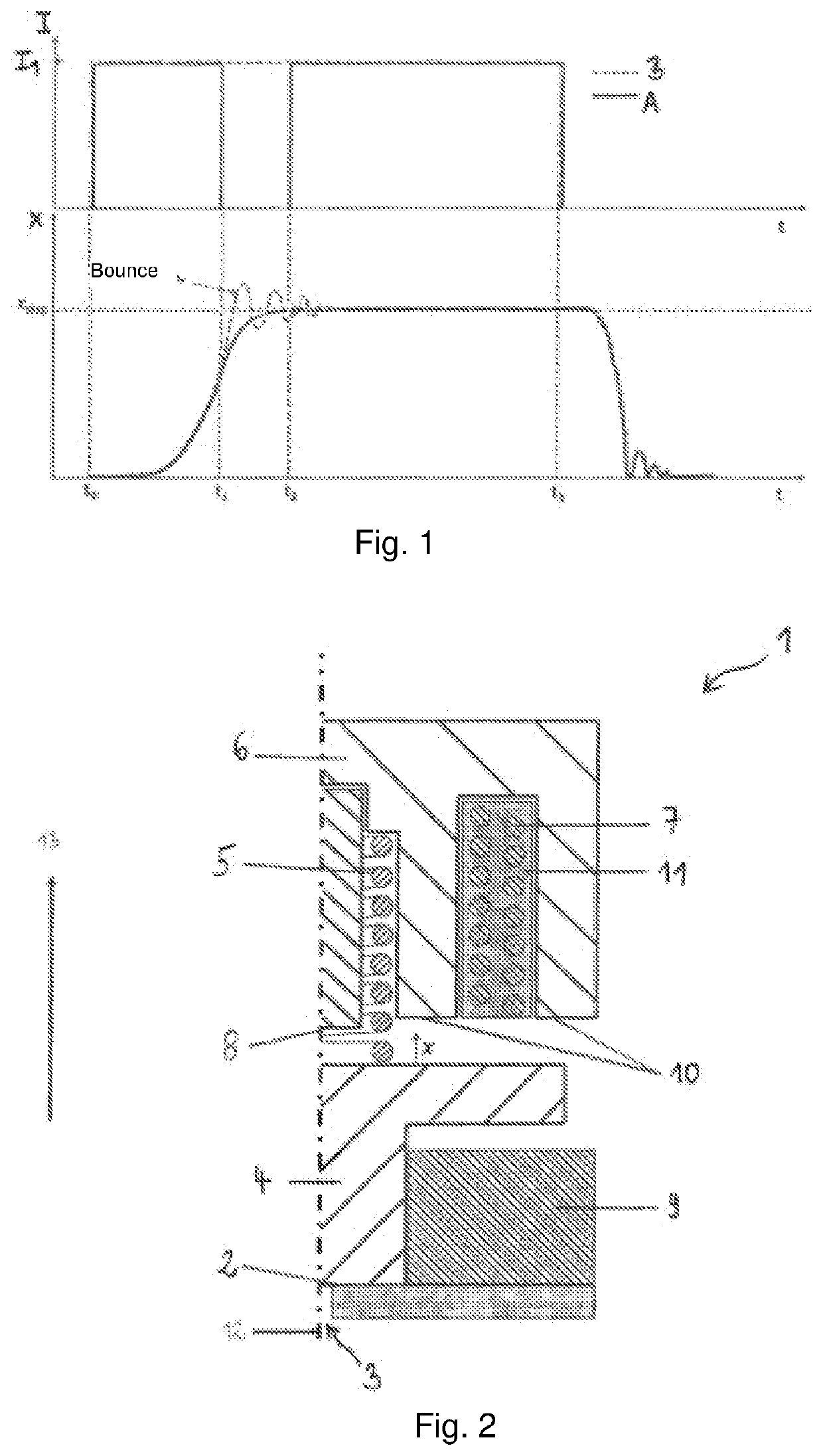
[0041]FIG. 1 shows two diagrams arranged above one another over the time t, with the upper one of the two diagrams showing the curve of a control signal I, or of the current supplied to the electromagnet in accordance with the disclosure (solid line A), and in accordance with the prior art (dashed line B). The diagram arranged therebelow shows the movement (x) of the armature element in dependence on the different control signals, with the dashed line representing the control behavior in accordance with the prior art and the continuous line showing the control in accordance with the disclosure.

[0042]It can be seen from the diagrams that the armature element lies on the seat plate at the time to so that the passage opening is sealed.

[0043]If now at the time to the current signal I for controlling the electromagnet is set to a value I1 that is different from zero and that has the result that the armature element is moved from the seat plate in the direction of a stroke-bounding abutme...


PUM


Abstract

The injector unit according to the disclosure comprises a seat plate with a through opening extending through the seat plate, an armature element which can be placed onto the seat plate, in order to close the through opening, a spring element pushing the armature element in the direction of the seat plate, in order to close the through opening, an electromagnet designed to load the armature element with a force, in order to lift the armature element from the seat plate, and a stop for limiting a stroke of the armature element in a state in which it is lifted from the seat plate. The injector unit is characterized by a control unit designed to reduce an actuating signal of the electromagnet for lifting the armature element from the seat plate before the armature element contacts the stop for the first time after being lifted from the seat plate.

Description

TECHNICAL FIELD[0001]The present disclosure relates to an injector unit for injecting fuel and to a method of operating same.BACKGROUND AND SUMMARY[0002]In internal combustion engines such as diesel engines or also gasoline engines a fuel is as a rule injected via an injector into a combustion chamber in a specific quantity and for a specific time period. It is necessary in this process due to the very short injection times that are in the microsecond range to open or close the outlet opening of the injector with a very high frequency.[0003]Since the basic functional principle of an injector is familiar to the skilled person, some aspects that are of advantage for the understanding of the disclosure will only be looked at briefly in the following.[0004]An injector typically has a nozzle needle (also: injector needle) that allows a highly pressurized fuel to exit outwardly on release of at least one discharge hole of the injector. This nozzle needle acts in cooperation with this at l...

Claims


Application Information

Patent Timeline
IPC IPC(8): F02M63/00F02D41/20F02M47/02
CPCF02M63/0017F02D41/20F02M47/027F02D2041/2058F02D2041/2024F02D2041/2037F02M63/0075
Inventor PIRKL, RICHARDSTINGHE, RAZVAN-SORINSEIDL, MARTIN
Owner LIEBHERR COMPONENTS DEGGENDORF GMBH
Why Eureka
Try Eureka