Method for controlling a water sluice gate drive for a water sluice gate having an electric machine, service connection, water sluice gate drive and hydroelectric power plant

a technology of water sluice gate and water sluice gate, which is applied in the direction of machines/engines, renewable energy generation, greenhouse gas reduction, etc., can solve the problems of destroying at least the guide and the bottom of the water sluice gate, and the protection device such as the vertical sluice gate having a comparatively high weight force must be swiftly set in motion, so as to reduce the cost of components

Inactive Publication Date: 2017-09-12
WOBBEN PROPERTIES GMBH
View PDF77 Cites 5 Cited by
  • Summary
  • Abstract
  • Description
  • Claims
  • Application Information

AI Technical Summary

Benefits of technology

[0012]One or more embodiments of the present invention are directed to a method and a device for controlling a water sluice gate drive having an asynchronous motor for a water sluice gate, in particular for a roller sluice gate, which ensures in the case of an emergency closure, the passive lowering of the vertical sluice gate, i.e., in particular without a power supply, even without mains supply and even without a safeguard of an uninterrupted power supply, and in so doing, nevertheless preventing the vertical sluice gate from stopping without braking or otherwise uncontrolled.
[0019]The method according to one embodiment of the invention has proven to be sufficiently reliable and at the same time practicable, in particular without avoiding further damage, even in the event of an absent power supply. The reliable and damage-free implementation of the method in an emergency closure situation, even in the absence of a mains supply and also when no uninterrupted power supply is available, is especially advantageous.
[0020]Within the context of an especially preferred further embodiment, in particular after the detection of an emergency closure situation, the method also comprises the following steps: detection of an insufficient, in particular absent, power supply. In particular the absence of line current or a line voltage respectively, and / or the absence of an uninterrupted power supply can be detected. The absence of an uninterrupted power supply may also occur because an uninterrupted power supply system (UPS) is not installed. An advantage of one or more embodiments of the invention described here is that the provision of an uninterrupted power supply system (UPS) is advantageously not necessary, since one or more embodiments of the invention makes the safe operation of the water sluice gate drive possible without line current or without line voltage even in an emergency closure situation; this leads to a reduction in components and costs.
[0038]It is especially preferred that a braking of the asynchronous machine (in the event that the asynchronous generator is operated in island operation) be done by connecting a first stage of load resistors. Brake control of the asynchronous machine may especially be done in a manner depending on voltage and / or depending on a position of the water sluice gate. It has proven to be particularly preferred that the asynchronous machine be regulated in at least two speed steps. In so doing, it has proven to be advantageous to connect a first and a second stage of load resistors depending on the voltage and / or depending on a position of the water sluice gate, in particular a first and a second stage of load resistors.
[0039]In the case of a water sluice gate drive, it has proven to be especially advantageous that the actuator unit have a gas spring accumulator, by means of which the fan brake may be disengaged. In addition, the actuator unit preferably has a control valve connected to a power source (i.e., during normal operation, with a mains supply or with a power supply from an uninterrupted electric circuit) in an actuator pressure line between the gas spring accumulator and the fan brake. Since the control valve is therefore open when not energized, the actuator unit ensures a supply of gas pressure to the fan brake by opening the control valve, which is open when not energized, in the actuator pressure line between the gas spring accumulator and the fan brake. Under the gas pressure, the fan brake can open automatically and in a self-actuated manner against a spring force of a brake spring of the fan brake and thereby release the rotor of the electric machine for a rotation in the stator; thus in order to generate a rotating field.

Problems solved by technology

In an operating situation, in particular an emergency closure situation, what is problematic on the one hand is that a protection device such as a vertical sluice gate having a comparatively high weight force must be swiftly set in motion.
Above all, movement of a vertical sluice gate and the control of a water sluice gate drive upstream therefrom is especially critical when the emergency closure situation coincides with a situation in which a power supply is no longer available for the water sluice gate drive; this situation proves to be especially problematic in the event that an electric machine, thus an electric motor / generator, is provided in the water sluice gate drive.
In such a situation, it would be expected that a vertical sluice gate of a water sluice gate that is being freely brought down during an emergency closure situation would cause massive damage to the guide of the vertical sluice gate at the point at which it impacts the ground; this would be due to the inertial forces of an impacting vertical sluice gate having a high weight.
For example, the forces of a 30 ton vertical sluice gate with a drop height of 10 m could result in the destruction of at least the guide and the bottom of the water sluice gate as well as possibly the vertical sluice gate itself.
In particular, the jamming of the aforementioned vertical sluice gate in the guide may be the undesired result.

Method used


Image

  • Method for controlling a water sluice gate drive for a water sluice gate having an electric machine, service connection, water sluice gate drive and hydroelectric power plant
  • Method for controlling a water sluice gate drive for a water sluice gate having an electric machine, service connection, water sluice gate drive and hydroelectric power plant
  • Method for controlling a water sluice gate drive for a water sluice gate having an electric machine, service connection, water sluice gate drive and hydroelectric power plant

Examples


Embodiment Construction

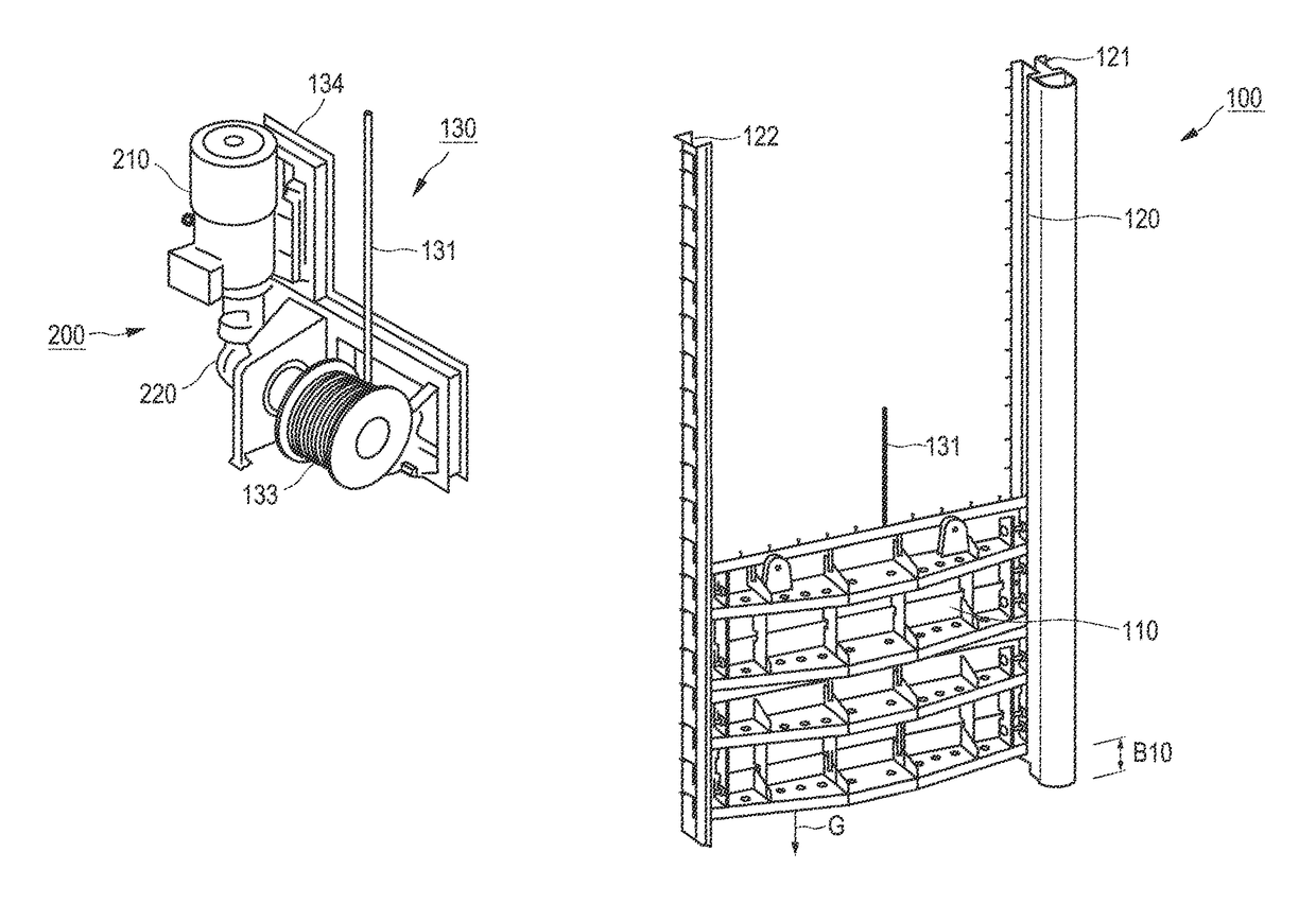
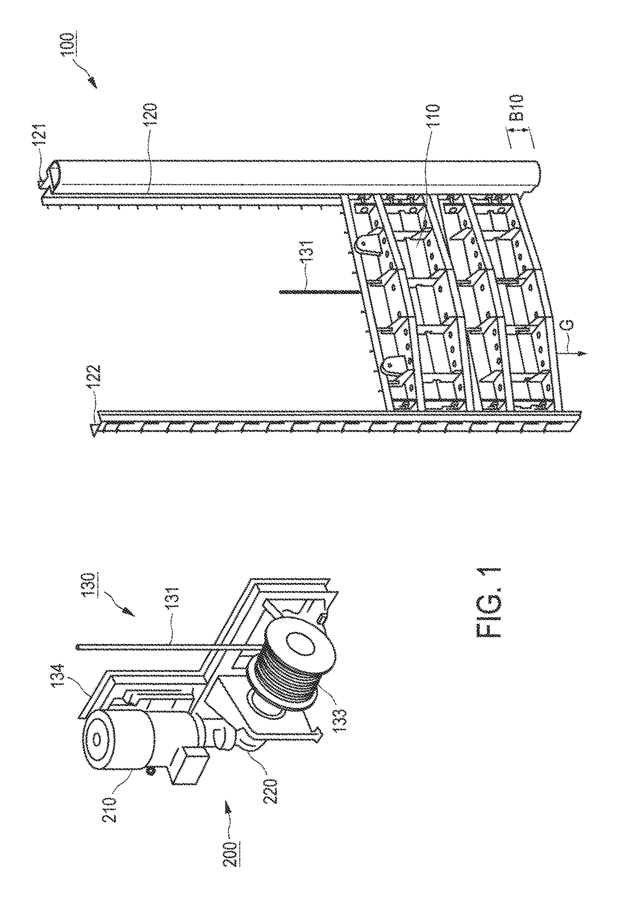
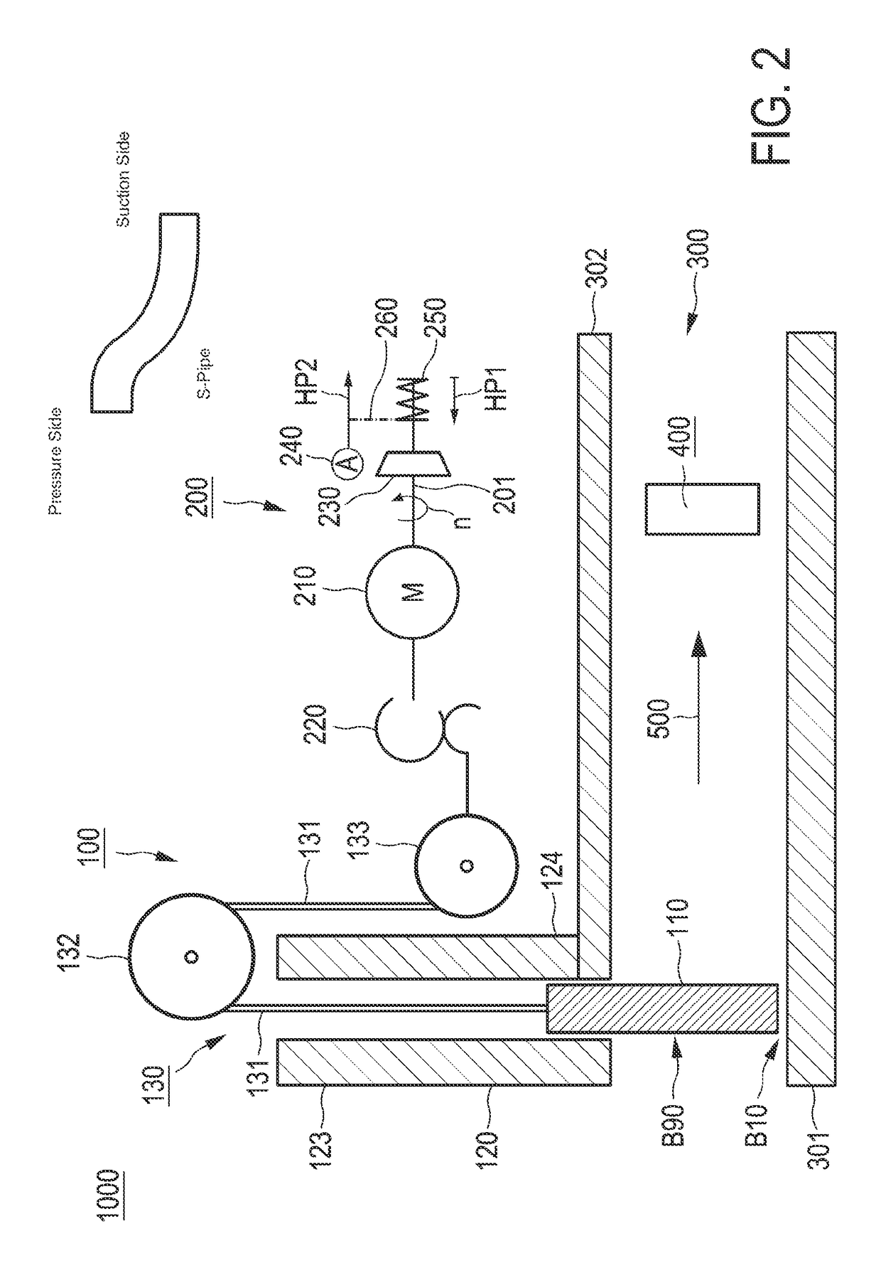
[0047]FIG. 1 shows a detail of an exemplary construction of a roller sluice gate for a hydroelectric power plant 1000 shown in greater detail in FIG. 2. In order to illustrate the water sluice gate 100 (here, a roller sluice gate), the weir has a vertical sluice gate 110 in a sluice gate mount 120 on a transmission winding mechanism 130. The sluice gate mount 120 has a first free-sliding rail 121 and a second free-sliding rail 122, which are designed each having a groove for the formation of a slide rail; the vertical sluice gate 110 is slidably mounted on both sides in the groove of the first and second free-sliding rails 121, 122. The vertical sluice gate 110 is held by a cord 131 of the transmission winding mechanism 130 from FIG. 2, wherein the cord 131, in the present case in the form of a cable, is guided from the vertical sluice gate 110 over guide rollers, specifically over a deflection roller 132, and over a cable drum 133 on a frame 101 of the transmission winding mechanis...


PUM


Abstract

The invention relates to a method for controlling a water sluice gate drive for a water sluice gate, in particular for a roller sluice gate, preferably in a hydroelectric power plant, wherein the drive has an electric machine, in particular has an asynchronous machine, in particular an asynchronous motor / generator. According to the invention, it is provided that the electric machine, in particular an asynchronous machine, has a fan brake, wherein the method comprises the steps of: disengagement of the fan brake in the case that an insufficient power supply is indicated, self-actuated operation of the electric machine, in particular an asynchronous machine, wherein the electric machine, in particular an asynchronous machine, is operated in generative island operation, in which a rotating field is generated in a self-actuating manner.

Description

BACKGROUND[0001]Technical Field[0002]The invention relates to a method for controlling a water sluice gate drive for a water sluice gate, in particular for a roller sluice gate, preferably in a hydroelectric power plant, wherein the drive has an asynchronous machine, in particular an asynchronous motor / generator. In addition, the invention relates to a service connection for controlling a water sluice gate drive for a water sluice gate. In addition, the invention relates to a water sluice gate drive and a hydroelectric power plant.[0003]Description of the Related Art[0004]A hydroelectric power plant is used to convert potential energy in water into electrical energy. In so doing, dammed up or running water in a water collection is fed in the direction of the current via a debris catcher and an inlet grill to a turbine, which is typically disposed in a turbine pipe, (e.g., suction pipe or pressure pipe), and said water thereby drives the turbine. The water leaving the turbine is fed ...

Claims


Application Information

Patent Timeline
Patent Type & Authority Patents(United States)
IPC IPC(8): H02P7/00E02B9/02E02B8/04H02P3/04F03B11/00E02B7/30E02B7/36H02P3/14H02P3/22H02P9/46
CPCE02B9/025E02B7/30E02B7/36E02B8/045E02B9/022E02B9/027F03B11/004H02P3/04H02P3/14H02P3/22H02P9/46Y02E10/22Y02E10/226Y02E10/20
Inventor JANSSEN, ANDREASUPHOFF, HEINRICH
Owner WOBBEN PROPERTIES GMBH
Why Eureka
Try Eureka