
Image forming apparatus

Inactive Publication Date: 2006-03-30
FUJIFILM CORP
View PDF7 Cites 46 Cited by
  • Summary
  • Abstract
  • Description
  • Claims
  • Application Information

AI Technical Summary

Benefits of technology

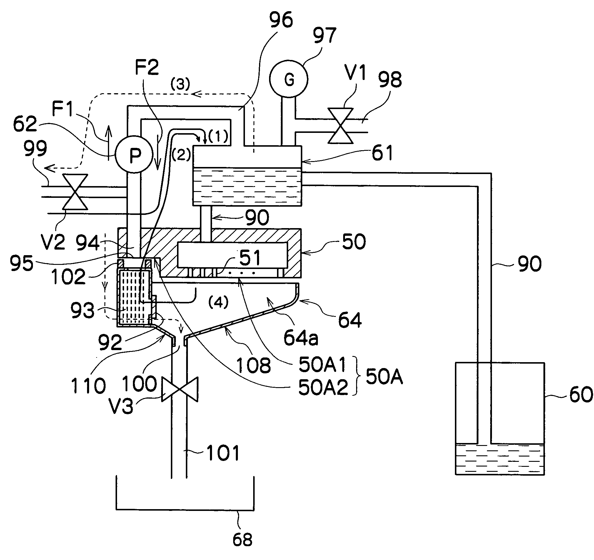
[0015] The present invention has been contrived in consideration of these circumstances, and it is an object thereof to provide an image forming apparatus in which a circulation system for returning a suctioned liquid to a sub-tank can be simplified, enabling space-saving.

Problems solved by technology

However, during printing the ink in the nozzles is exposed to the air, and hence the ink in a nozzle from which ejection is not performed for a long time dries, leading to an increase in the viscosity (thickening) of the ink.
As a result, the nozzle may become blocked, the ink in the nozzle may disappear, and hence ejection may become impossible.
Further, when bubbles that have become mixed into the ink supply passage and so on accumulate in front of a foreign matter removal filter disposed in the ink ejection head or ink supply passage, the accumulated bubbles may block the ink supply so that the ink cannot be ejected from the nozzles.
However, in the conventional inkjet printer having an ink circulation path described in Japanese Patent Application Publication No. 2003-266745, the ink circulation path for returning the ink suctioned into the cap to the sub-tank is wound around the outside of the head, and therefore the ink circulation path is long and complicated, disposal space must be secured for the ink circulation path, and there is a high likelihood of bubbles merging with the ink through the circulation path, which is constituted by a tube or the like.
Furthermore, in the prior art the pump which circulates the ink and a pump which adjusts the internal pressure of the sub-tank are provided separately rather than being constituted by a single pump, making the apparatus constitution complicated and preventing size reductions.

Method used


Image

  • Image forming apparatus
  • Image forming apparatus
  • Image forming apparatus

Examples


Embodiment Construction

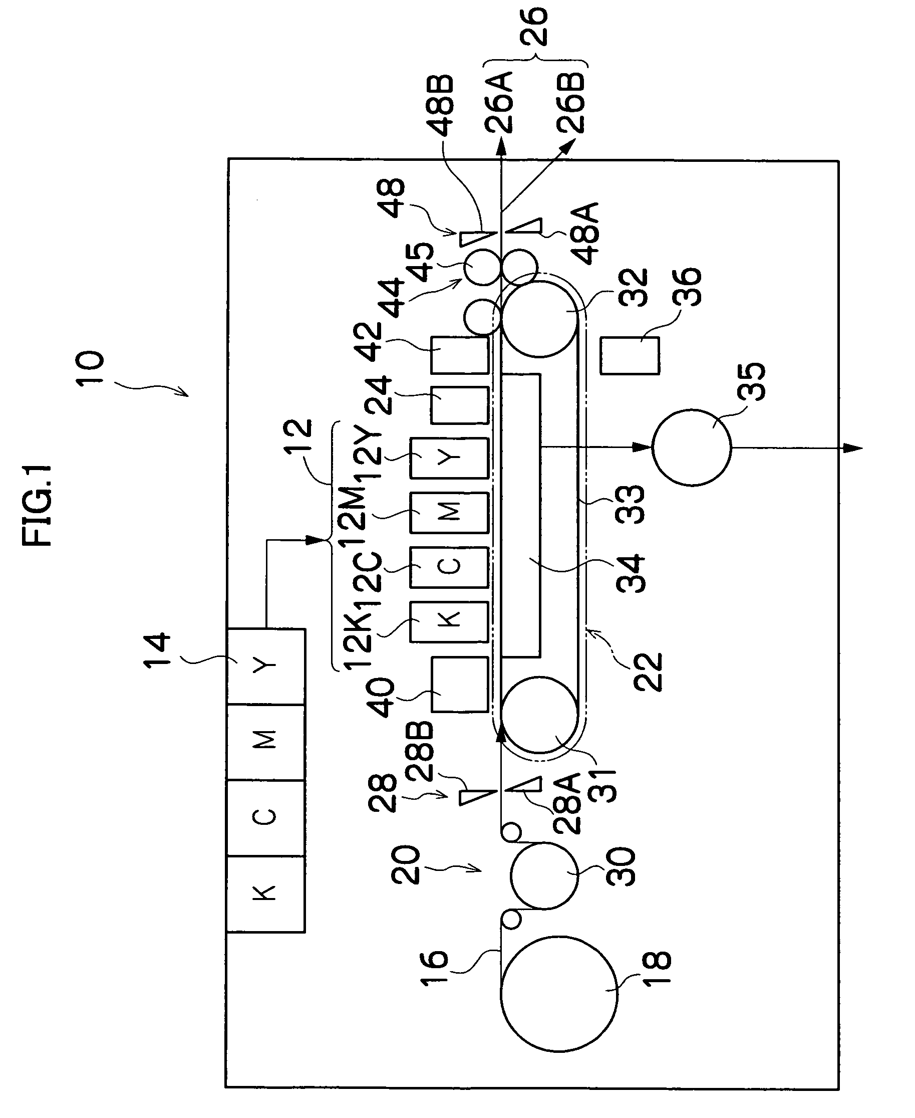
[0050]FIG. 1 is a general schematic drawing showing an embodiment of an inkjet recording apparatus serving as an image forming apparatus according to the present invention.

[0051] As shown in FIG. 1, an inkjet recording apparatus 10 comprises a print unit having a plurality of print heads (inkjet recording heads) 12K, 12C, 12M, 12Y provided for each ink color, an ink storing and loading unit 14 in which the ink supplied to the print heads 12K, 12C, 12M, 12Y is stored, a paper supply unit 18 which supplies recording paper 16, a decurling unit 20 which removes curls from the recording paper 16, a suction belt conveyance unit 22 disposed opposite a nozzle face (ink ejection face) of the print unit 12 for conveying the recording paper 16 while maintaining the flatness of the recording paper 16, a print determination unit 24 which reads printing results generated by the print unit 12, and a paper output unit 26 which outputs the printed recording paper (printed object) to the outside.

[0...


PUM


Abstract

The image forming apparatus comprises: an ejection head which includes a plurality of nozzles to eject a liquid to deposit the liquid on a recording medium being conveyed relatively to the ejection head to form an image on the recording medium; a tank which stores the liquid to be supplied to the nozzles and has an adjustable internal pressure; a liquid supply path which connects the tank and the ejection head; a cap which faces a nozzle face on which the nozzles of the ejection head are formed; a liquid collection path which is capable of connecting the cap and the tank; and a liquid circulating device which is provided on the liquid collection path, collects the liquid in the ejection head through the cap, circulates the liquid to the tank along the liquid collection path, and adjusts the internal pressure of the tank to a desired value.

Description

BACKGROUND OF THE INVENTION [0001] 1. Field of the Invention [0002] The present invention relates to an image forming apparatus, and more particularly to an image forming apparatus which forms images by depositing a liquid such as ink onto a recording medium from an ejection head. [0003] 2. Description of the Related Art [0004] An inkjet recording apparatus (inkjet printer) having an ink ejection head (print head) in which a large number of nozzles are arranged is known as a conventional image forming apparatus. This inkjet recording apparatus forms an image on a recording medium by ejecting ink in the form of liquid droplets from the nozzles of the ink ejection head onto the recording medium while moving the ink ejection head relatively to the recording medium. [0005] Various conventional methods are known for ejecting the ink in this type of inkjet recording apparatus. Known examples of ink ejection methods include a piezoelectric method, in which a diaphragm constituting a part o...

Claims


Application Information

Patent Timeline
IPC IPC(8): B41J2/18
CPCB41J2/18B41J2/16508
Inventor INOUE, HIROSHI
Owner FUJIFILM CORP
Learn More