Rear projection television

a technology of rear projection and television, which is applied in the field of rear projection television, can solve the problems of poor productivity, ejection machine cannot smoothly release the molding from the die, and the patent document 1 fails to achieve a better cooling efficiency, so as to suppress an increase in temperature and supply smooth

Inactive Publication Date: 2006-03-30
ORION ELECTRIC CO LTD
View PDF5 Cites 11 Cited by
  • Summary
  • Abstract
  • Description
  • Claims
  • Application Information

AI Technical Summary

Benefits of technology

[0016] With the configuration according to the third aspect, the housing is provided not only with the intake port through which external air is supplied to the interior of the housing but also wit

Problems solved by technology

However, in efficiently releasing heat from a heating element that becomes hotter than electronic parts or the like, the patent document 1 fails to achieve a better cooling efficiency than, for example, a fan that forcibly exhausts air.
However, since both apparatuses are provided with the

Method used


Image

  • Rear projection television
  • Rear projection television
  • Rear projection television

Examples


Embodiment Construction

[0024] With reference to FIGS. 1 to 7, description will be given of an embodiment that is the best mode for carrying out the present invention. Of course, it is needless to say that the present invention can also be easily applied to configurations different from those described in the embodiment without departing from the spirit of the present invention.

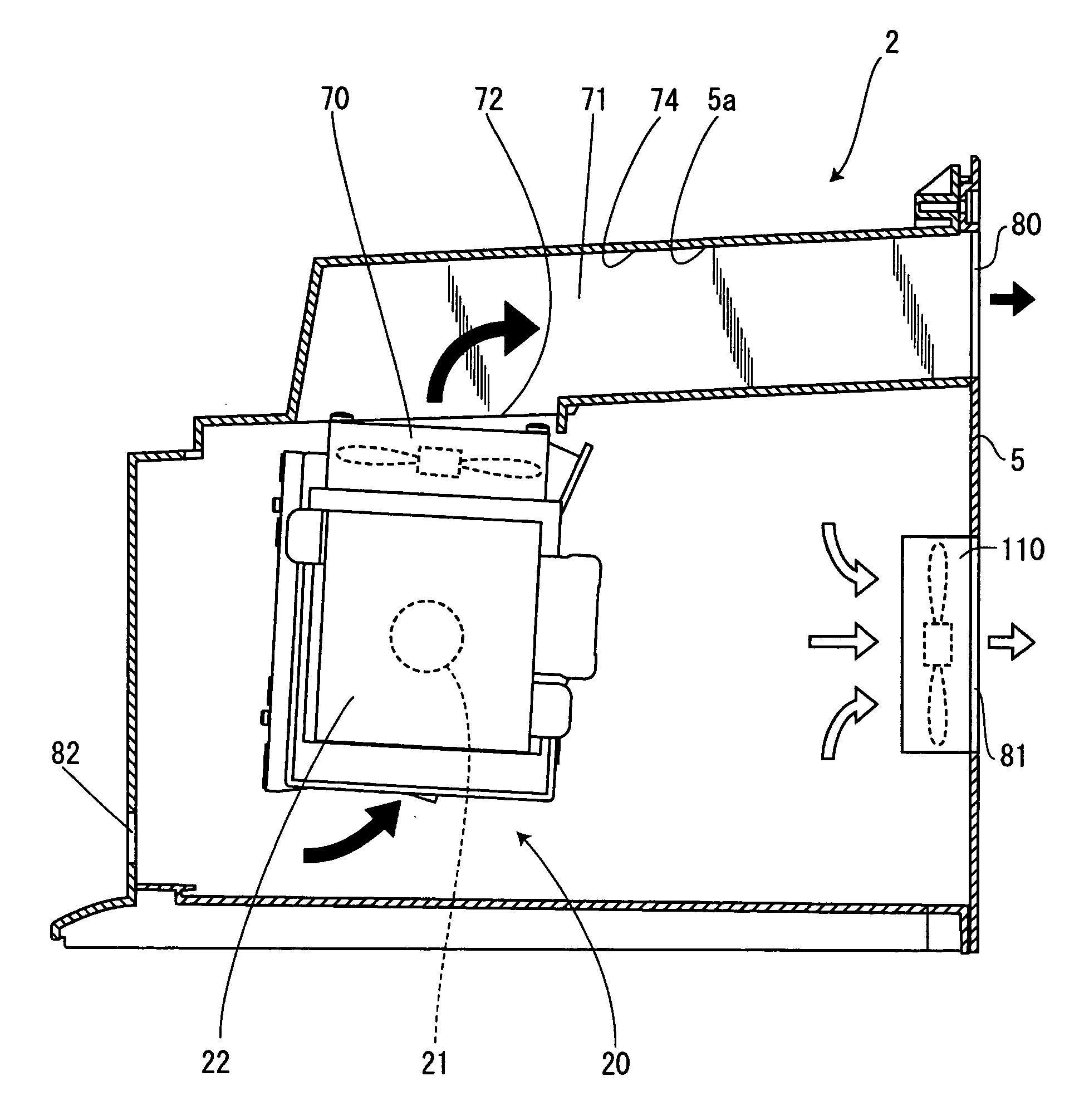
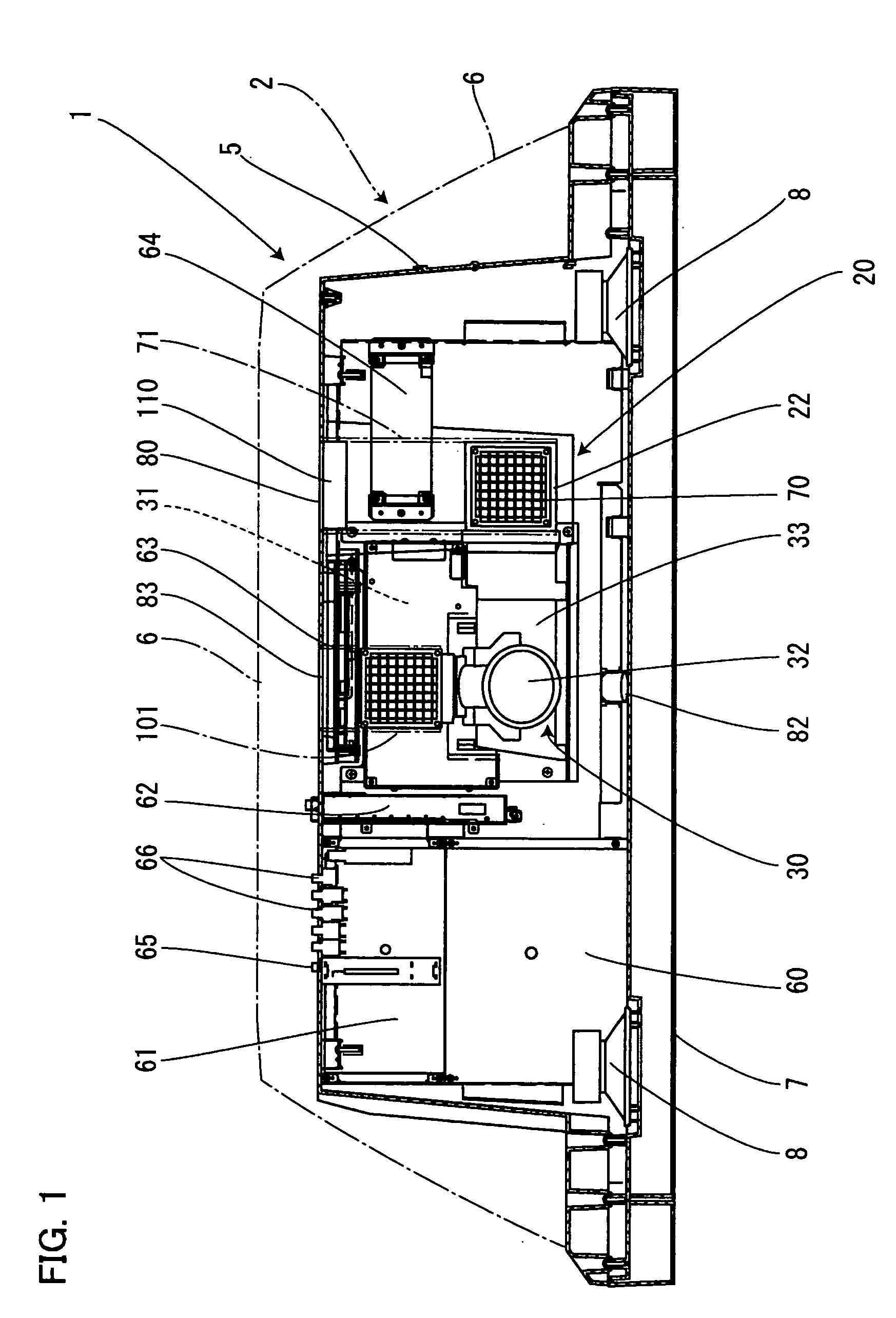
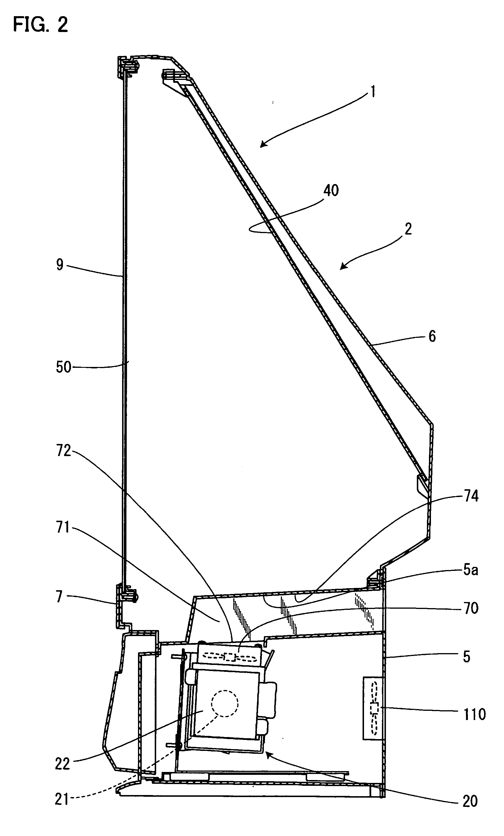
[0025]FIG. 1 is a top sectional view schematically showing the configuration of a rear projection television according an embodiment of the present invention as viewed from above. FIG. 2 is a schematic sectional view mainly showing a lamp housing section in the rear projection television. FIG. 3 is an enlarged view showing the vicinity of a lamp unit. FIG. 4 is a perspective view showing a first duct. FIG. 5 is a schematic sectional view mainly showing a lamp unit. FIG. 6 is an enlarged view showing the vicinity of a heating element. FIG. 7 is a perspective view showing a second duct.

[0026] With reference to these figures, descrip...


PUM


Abstract

The present invention provides an inexpensive rear projection television including a cooling structure that blows air directly against a heating element that generates heat to become hot, thus suppressing a rise in the temperature of the heating element. In addition, the shapes of having exhaust ducts are simplified, thus reducing the cost. A first duct 71 and a second duct 101 are formed to have generally U-shaped cross sections; air blown by a first blowing fan 70 is exhausted to the exterior through the first duct 71 and external air is supplied to a second blowing fan 100 through the second duct 101. The U-shaped opening sides of the ducts are attached to a lower cabinet 5 to form cylindrical paths. Consequently, the costs of the ducts are lower than those of integrally cylindrically molded ducts.

Description

[0001] The present application is based on and claims priority of Japanese patent application No. 2004-286455 filed on Sep. 30, 2004, the entire contents of which are hereby incorporated by reference. BACKGROUND OF THE INVENTION [0002] 1. Field of the Invention [0003] The present invention relates to a rear projection television that reflectively projects an optical image projected by a projection unit on a screen exposed from a side surface of a housing. [0004] 2. Description of the Related Art [0005] Japanese Patent Laid-Open Publication No. 2002-199307 (Patent Document 1) proposes a rear projection television having a through-hole formed in a cabinet and through which heat generated by an electronic circuit is released; the electronic circuit is a heating element provided in the cabinet. [0006] Japanese Patent Laid-Open Publication No. 11-41547 (Patent Document 2) discloses a structure in which a projection device main body including a light source lamp, a heating element, by usi...

Claims


Application Information

Patent Timeline
IPC IPC(8): H04N5/74
CPCG03B21/10H04N9/3141G03B21/16
Inventor TAJIMA, KOICHISHIMOSHITA, KENJITOKUDA, TAKASHI
Owner ORION ELECTRIC CO LTD
Why Eureka
Try Eureka