In-vehicle control apparatus

Active Publication Date: 2021-07-15
TOYOTA JIDOSHA KK
View PDF0 Cites 0 Cited by
  • Summary
  • Abstract
  • Description
  • Claims
  • Application Information

AI Technical Summary

Benefits of technology

[0012]With this configuration, when the degree of wear and tear is higher than or equal to the prescribed determination value, the engagement operation of the synchromes

Problems solved by technology

Incidentally, with the configuration described in JP 2019-039453 A, unless abrasion of the synchronizer ring increases to some extent, the degree of wear and tear due to such abrasion is not

Method used


Image

  • In-vehicle control apparatus
  • In-vehicle control apparatus
  • In-vehicle control apparatus

Examples


Embodiment Construction

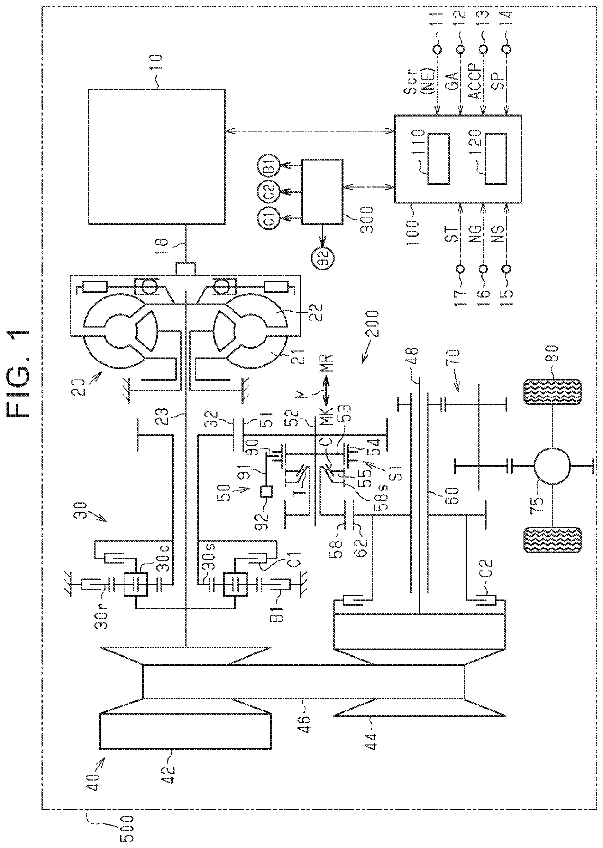
[0020]Hereinafter, an embodiment of an in-vehicle control apparatus will be described with reference to FIG. 1 to FIG. 5. As shown in FIG. 1, a vehicle 500 includes an internal combustion engine 10 and a powertrain 200 that transmits the output torque of the internal combustion engine 10 to drive wheels 80.

[0021]The powertrain 200 includes a torque converter 20, an input shaft 23, a belt-type continuously variable transmission 40, a switching mechanism 30, a gear transmission mechanism 50, an output shaft 60, a reduction gear 70, a differential gear 75, the drive wheels 80, and the like. The torque converter 20 is a fluid transmission device to which a crankshaft 18 of the internal combustion engine 10 is connected. The input shaft 23 is connected to the torque converter 20. The belt-type continuously variable transmission 40 is connected to the input shaft 23. The switching mechanism 30 is connected to the input shaft 23. The gear transmission mechanism 50 is connected to the input...


PUM


Abstract

An in-vehicle control apparatus is configured to execute a collision degree calculation process of, when it is determined that gear rattle occurs, calculating a collision degree that indicates a magnitude of a collision between a sleeve chamfer and a gear chamfer based on a rotation speed difference between a sleeve and an idler gear, execute an index value calculation process of calculating an index value that correlates with wear and tear of the sleeve chamfer and the gear chamfer based on the collision degree that is calculated each time it is determined that gear rattle occurs, and execute a wear and tear degree calculation process of calculating a degree of wear and tear of the sleeve chamfer and the gear chamfer by integrating the index value that is calculated each time it is determined that gear rattle occurs.

Description

INCORPORATION BY REFERENCE[0001]The disclosure of Japanese Patent Application No. 2020-002692 filed on Jan. 10, 2020 including the specification, drawings and abstract is incorporated herein by reference in its entirety.BACKGROUND1. Technical Field[0002]The disclosure relates to an in-vehicle control apparatus.2. Description of Related Art[0003]For example, Japanese Unexamined Patent Application Publication No. 2019-039453 (JP 2019-039453 A) describes a synchromesh mechanism. The synchromesh mechanism includes an idler gear provided so as to be rotatable relative to a shaft, a sleeve movable in an axial direction of the shaft, and a synchronizer ring that synchronizes the rotation of the idler gear with the rotation of the sleeve.[0004]In JP 2019-039453 A, the degree of abrasion of the synchronizer ring that is a synchronization element is estimated based on a difference between a sleeve position at the start of synchronization where the sleeve contacts with the synchronizer ring an...

Claims


Application Information

Patent Timeline
IPC IPC(8): F16D23/02F16D11/10B60K17/04F16D11/00F16D23/12
CPCF16D23/025F16D11/10B60K17/04F16D2500/10456F16D2300/18F16D23/12F16D2011/002F16H61/12F16H61/16F16H2061/1208F16H2061/1256F16H2061/1276F16H9/00F16D23/04F16D48/06F16D2500/30415F16D2500/30426F16D2500/5023F16D2500/70402
Inventor SEO, TAKASHI
Owner TOYOTA JIDOSHA KK
Why Eureka
Try Eureka