Check patentability & draft patents in minutes with Patsnap Eureka AI!

Viewing angle control apparatus

a control apparatus and viewing angle technology, applied in non-linear optics, instruments, optics, etc., can solve the problems of difficult switching to the wide viewing angle display, difficult for many persons to view display contents, etc., and achieve the effect of high visibility

Inactive Publication Date: 2006-03-30
KK TOSHIBA
View PDF6 Cites 17 Cited by
  • Summary
  • Abstract
  • Description
  • Claims
  • Application Information

AI Technical Summary

Benefits of technology

The present invention is about a device that controls the viewing angle of a display screen to prevent others from spying or watching from an oblique direction. The device includes a first transparent substrate with a first transparent electrode, a first alignment film with different alignment directions, a liquid crystal layer, a second alignment film with different alignment directions, and a second transparent substrate with a second transparent electrode. By applying a voltage to the electrodes, the device controls the transmittance ratio of different regions and the alignment film from the normal direction. This results in a high visibility from the front direction and prevents unwanted viewing or spying from the oblique direction. The technical effect of the invention is to provide a viewing angle control apparatus that maintains high visibility while preventing others from spying or watching from an oblique direction.

Problems solved by technology

The viewing feature makes it difficult for many persons to view display contents.
Accordingly, this display apparatus is applied to the narrow viewing angle display only, and switching to the wide viewing angle display is difficult.

Method used


Image

  • Viewing angle control apparatus
  • Viewing angle control apparatus
  • Viewing angle control apparatus

Examples


embodiment 1

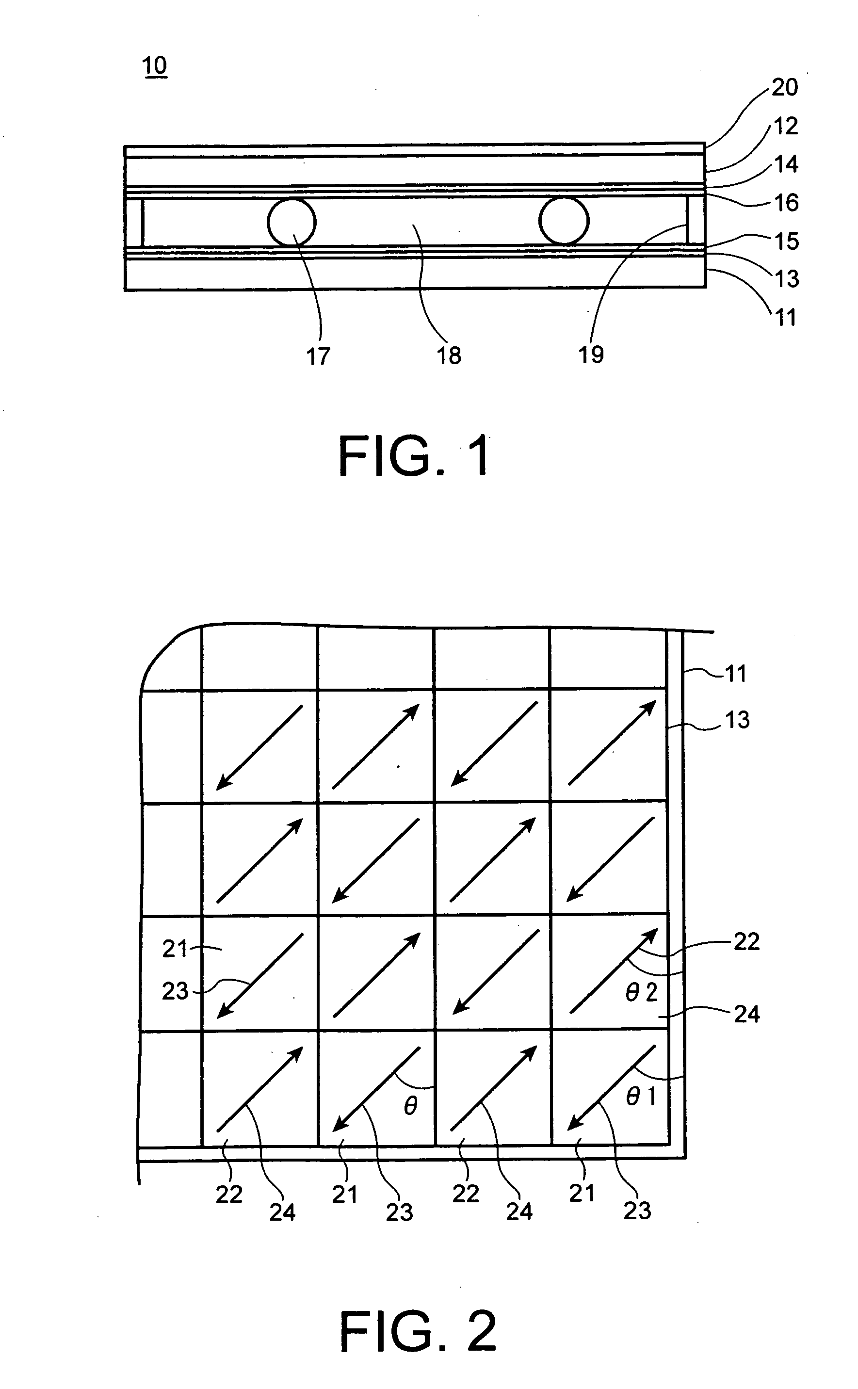
[0062] First, two glass substrates (thickness 0.7 mm) of diagonal line 7 inch on which an ITO thin film (film thickness 500 Å) is formed are prepared. After cleaning the two glass substrates, polyimide AL1051 for liquid crystal alignment film is coating by a spin coat. Then, the two glass substrates are baked in a clean oven at 200° C. for one hour. As a result, two polyimide alignment films of which film thickness is about 500˜1000 Å are obtained.

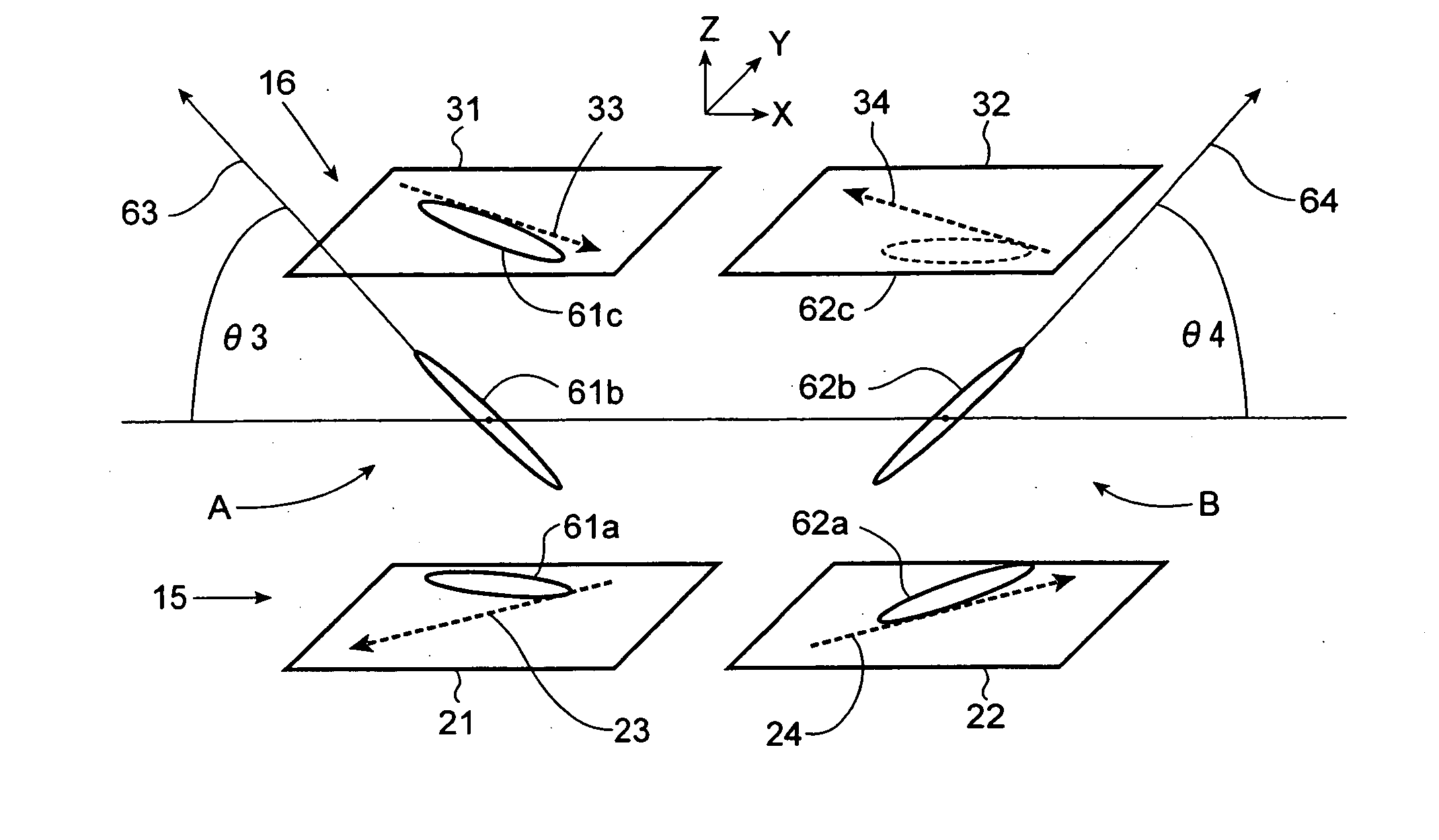
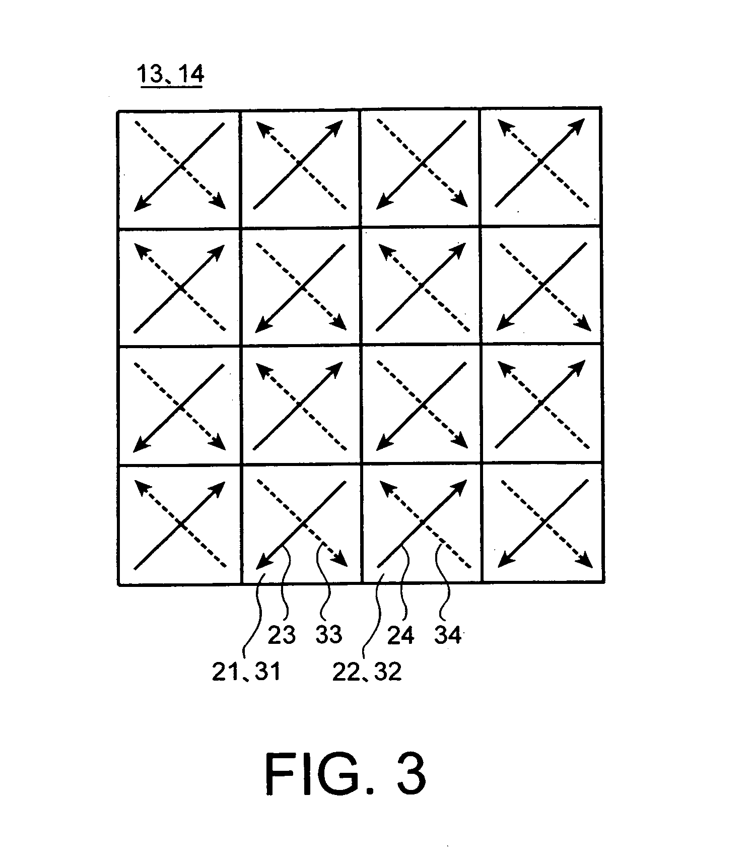
[0063] Next, alignment processing by rubbing is executed. In this case, alignment processing by mask rubbing is executed so that two regions each having different direction are mutually arranged. First, uniform rubbing processing is executed on all surface of the polyimide film of upper side substrate. Next, a metal mask on which square patterns (one side is 4 mm) are formed is placed on the upper side substrate. By mask rubbing, two regions of which rubbing directions are different are obtained.

[0064] On the upper side substrate, epoxy ...

embodiment 2

[0067] A viewing angle control apparatus is manufactured on condition that the liquid crystal material 18 is ZLI5049 and Δn·d of the liquid crystal layer is 2 μm by a gap spacer 10 μm. Other conditions are the same as in embodiment 1. By adjusting a voltage so that the pattern contrast from oblique (30°) direction is 5, display contents are not recognized, the pattern (checkers) on a screen from the front direction is not recognized, and sufficient brightness display of the screen from the front direction is obtained. Furthermore, the screen from an oblique (above 40°) direction is dark and the display contents cannot be sufficiently recognized from the oblique direction. In case of measuring a pattern contrast from the front direction, the pattern contrast is 1.1 and the brightness is 95% compared with the initial brightness (non-applying status of voltage).

embodiment 3

[0068] A viewing angle control apparatus is manufactured on condition that the liquid crystal material 18 is MJ29870 and Δn·d of the liquid crystal layer is 2.5 μm by a gap spacer 14 μm. Other conditions are the same as in embodiment 1. By adjusting a voltage so that the pattern contrast from oblique (30°) direction is 7, the pattern contrast 8 of the screen from the oblique (40°) direction is obtained, which is effective to avoid spying. On the other hand, patterns (checkers) on the screen from the front direction are not recognized, and display contents on the screen can be sufficiently seen from the front direction. In case of measuring a pattern contrast from the front direction, the pattern contrast is 1.07 and the brightness is 92% compared with the initial brightness. As a result, a viewing angle control apparatus having good features is obtained.


PUM

PropertyMeasurementUnit
transmittanceaaaaaaaaaa
angleaaaaaaaaaa
angleaaaaaaaaaa

Abstract

A first alignment film includes a plurality of first regions and second regions. A second alignment film includes a plurality of third regions and fourth regions. The third region corresponds to the first region and the fourth region corresponds to the second region. Alignment directions of the first region, the second region, the third region, and the fourth region are different. By applying a voltage, a transmittance ratio of the first region and the second region is above 5 in an angle range above 30° and below 40° from a normal direction, and a transmittance of the first alignment film from the normal direction is above 90% of the transmittance in case of non-applying the voltage.

Description

CROSS-REFERENCE TO RELATED APPLICATIONS [0001] This application is based upon and claims the benefit of priority from prior Japanese Patent Application P2004-285291, filed on Sep. 29, 2004; the entire contents of which are incorporated herein by reference. FIELD OF THE INVENTION [0002] The present invention relates to a viewing angle control apparatus for changing a viewing angle of a display screen by applying a voltage. BACKGROUND OF THE INVENTION [0003] A liquid crystal display apparatus uses a liquid crystal material having optical anisotropy. Accordingly, the liquid crystal display apparatus has a different visibility feature (viewing feature) based on a viewing angle. The viewing feature makes it difficult for many persons to view display contents. On the other hand, the viewing feature is utilized to secure secret information or personal information. Briefly, by using the viewing feature, displayed contents are visible from a front direction, but are not visible from an obliq...

Claims


Application Information

Patent Timeline
Patent Type & Authority Applications(United States)
IPC IPC(8): G02F1/1337
CPCG02F1/1323G02F2001/133757G02F1/13471G02F1/133753G02F1/133757G02F1/1337G02F1/1335
Inventor HOTTA, AIRATANAKA, MASAOTAKATO, KOKI
Owner KK TOSHIBA
Features
  • R&D
  • Intellectual Property
  • Life Sciences
  • Materials
  • Tech Scout
  • Unparalleled Data Quality
  • Higher Quality Content
  • 60% Fewer Hallucinations
Learn More