Side emitting device, backlight unit using the same as light source and liquid crystal display employing the backlight unit

a backlight unit and side emitting technology, which is applied in the direction of semiconductor devices for light sources, lighting and heating devices, instruments, etc., can solve the problems of inconvenient backlighting of conventional side emitting leds and interference between adjacent leds

Inactive Publication Date: 2006-03-30
SAMSUNG ELECTRONICS CO LTD
View PDF4 Cites 66 Cited by
  • Summary
  • Abstract
  • Description
  • Claims
  • Application Information

AI Technical Summary

Benefits of technology

[0011] The present general inventive concept provides a side emitting device which enables light to be uniformly mixed when the side emitting devices are used by a backlight unit and interference between adjacent sources does not occur, a backlight unit using the side emitting devices as light sources, and an image display apparatus employing the backlight unit.
[0028] The backlight unit may further comprise at least one of a brightness enhancement film to enhance directionality of the light emitted from the first transmission diffusion plate and a polarization enhancement film to enhance polarization efficiency.

Problems solved by technology

Since the conventional side emitting LED emits light sideways, when the conventional side emitting LEDs are arranged in an array, adjacent LEDs may interfere with each other.
Accordingly, the conventional side emitting LED is not suitable for backlight units.

Method used


Image

  • Side emitting device, backlight unit using the same as light source and liquid crystal display employing the backlight unit
  • Side emitting device, backlight unit using the same as light source and liquid crystal display employing the backlight unit
  • Side emitting device, backlight unit using the same as light source and liquid crystal display employing the backlight unit

Examples


Embodiment Construction

[0037] Reference will now be made in detail to the embodiments of the present general inventive concept, examples of which are illustrated in the accompanying drawings, wherein like reference numerals refer to the like elements throughout. The embodiments are described below in order to explain the present general inventive concept while referring to the figures.

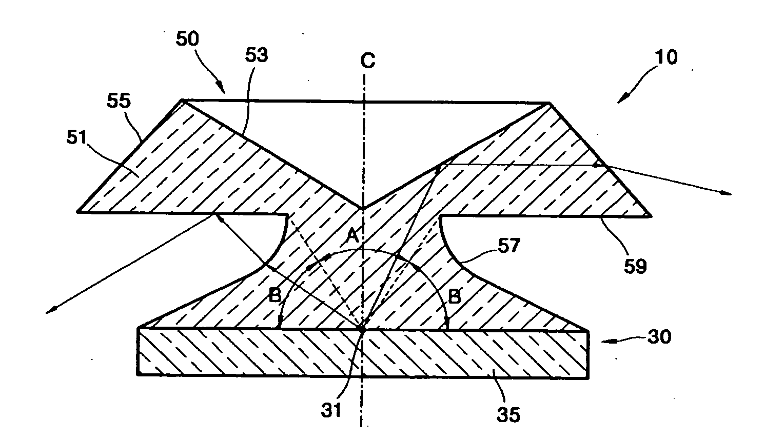
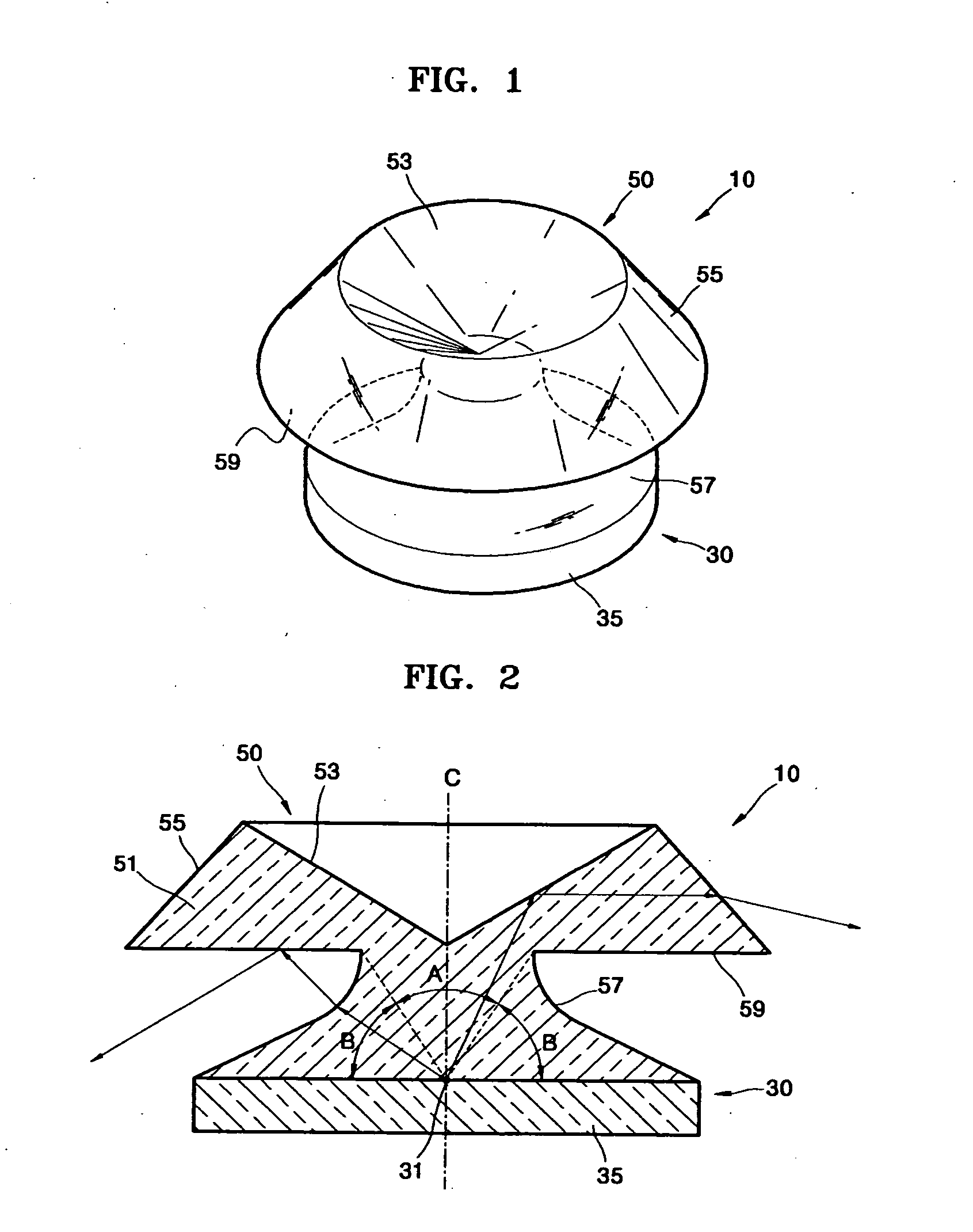
[0038]FIG. 1 is a schematic perspective view of a side emitting device 10 according to an embodiment of the present general inventive concept. FIG. 2 is a side view of the side emitting device illustrated in FIG. 1.

[0039] Referring to FIGS. 1 and 2, the side emitting device 10 includes a light-emitting device 30, and a side emitter 50 directing light incident from the light-emitting device 30 obliquely downward.

[0040] Here, when a main direction of the light emitted from the light-emitting device 30 is referred to as an upward direction, a downward will be referred to as a direction opposite to the upward direction. Here,...


PUM


Abstract

A side emitting device, a backlight unit using the same as a light source, and a liquid crystal display (LCD) employing the backlight unit. The side emitting device includes a light-emitting device to emit light, and a side emitter to change the path of at least part of the light emitted from the light-emitting device. The side emitter includes a first reflecting surface reflecting light emitted from the light-emitting device in a first range of angles close to a central axis, a first refracting surface refracting the light reflected by the first reflecting surface obliquely downward from the horizontal axis, and a second refracting surface refracting light emitted from the light-emitting device in a second range of angles complementary to the first range of angles. The backlight unit includes at least an array of side emitting devices, a reflection diffusion plate and a first transmission diffusion plate.

Description

CROSS-REFERENCE TO RELATED APPLICATIONS [0001] This application claims the benefit of priority under U.S.C. § 119 from Korean Patent Application No. 2004-77595, filed on Sep. 25, 2004, in the Korean Intellectual Property Office, the disclosure of which is incorporated herein in its entirety by reference. BACKGROUND OF THE INVENTION [0002] 1. Field of the Invention [0003] The present general inventive concept relates to a side emitting device, a backlight unit using the same as a light source, and an image display apparatus employing the backlight unit. [0004] 2. Description of the Related Art [0005] Liquid crystal displays (LCDs), a type of flat panel display, are light receiving displays in which an image is produced not by self-emission but by external light. The LCDs need external light sources to display images since the LCDs themselves do not directly emit light. When using LCDs, backlight units are installed at a rear side of the LCDs to illuminate the LCDs. [0006] The backlig...

Claims


Application Information

Patent Timeline
Patent Type & Authority Applications(United States)
IPC IPC(8): F21V5/00H01L33/54H01L33/60
CPCF21K9/00F21V5/02F21V7/0091F21Y2101/02G02F1/133603G02B19/0061H01L33/54H01L33/60G02B19/0071G02B19/0028G02F1/133609F21Y2115/10F21K9/68G02F1/1335
Inventor NOH, JI-WHANPARK, JOON-CHANKIM, DONG-HAWANG, JONG-MINHWANG, JU-SEONG
Owner SAMSUNG ELECTRONICS CO LTD
Why Eureka
Try Eureka