Computing optimal channel allocations using decomposition methods and related devices

a decomposition method and channel allocation technology, applied in the field of computing optimal channel allocation using decomposition methods, can solve the problem of requiring a long period of time to compute actual channel allocation

Active Publication Date: 2006-03-30
RPX CORP +1
View PDF6 Cites 17 Cited by
  • Summary
  • Abstract
  • Description
  • Claims
  • Application Information

AI Technical Summary

Benefits of technology

[0010] Because each formed subgraph represents an interference pattern of a small WLAN, it is possible to optimally allocate channels to each subgraph within a reasonable time period. It is also possible to assign channels to the entire WLAN, represented by the many subgraphs, within a reasonable time period.

Problems solved by technology

Practically speaking, except for very small WLANs (i.e. those with only a few APs) the solutions presented in U.S. patent application Ser. No. ______ may require a long period of time to compute the actual channel allocations.

Method used


Image

  • Computing optimal channel allocations using decomposition methods and related devices
  • Computing optimal channel allocations using decomposition methods and related devices
  • Computing optimal channel allocations using decomposition methods and related devices

Examples


Embodiment Construction

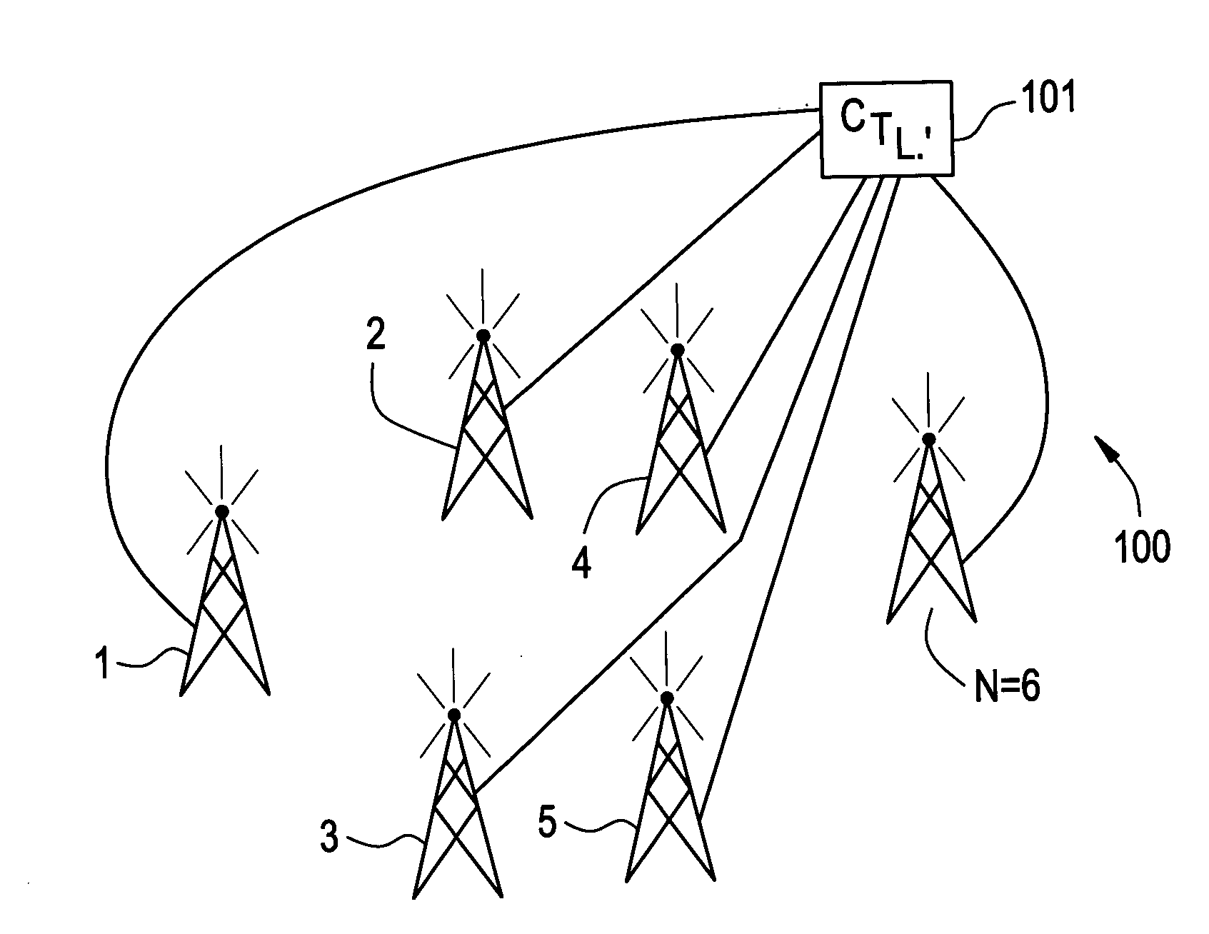
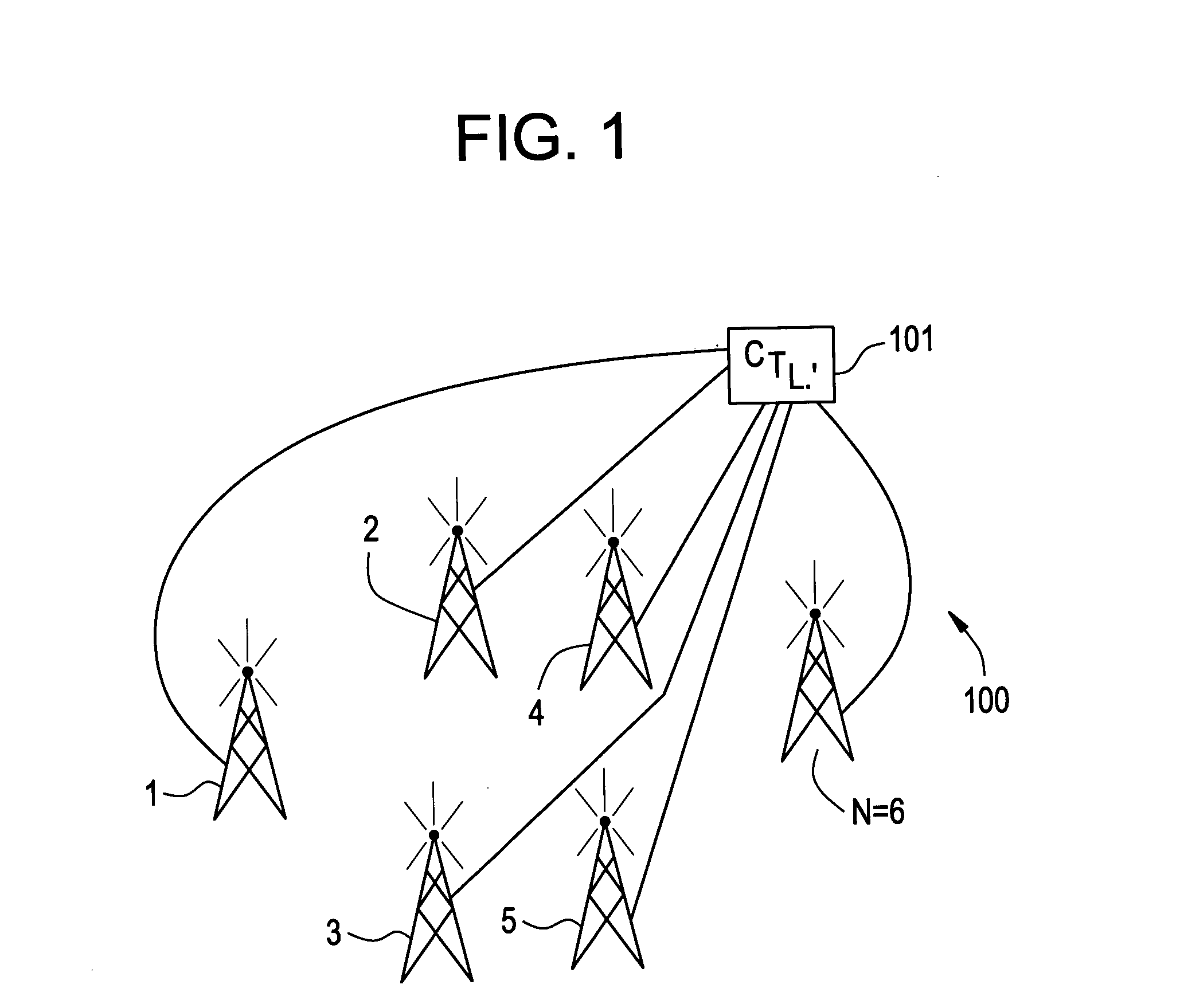
[0014] Referring now to FIG. 1, there is shown a simplified diagram of APs 1, 2, . . . N making up a WLAN 100. Also shown is a controller 101 operable to control each of the APs. In one embodiment of the present invention when the APs are base stations, the controller 101 may comprise a base station controller. The controller 101 is operable to carry out the features and functions of the present invention discussed above and below in an attempt to allocate a channel to each AP 1,2, . . . N within a reasonable time period using approximations of an optimal channel allocation scheme.

[0015] Before discussing details of the present invention, it should be understood that the present invention adopts the frame-based channel allocation architecture disclosed in U.S. application Ser. No. ______ referred to above. In this architecture, only those APs that are allocated a channel during a time frame, t, are allowed to transmit. Those APs that are not allocated a channel are not permitted to...


PUM


Abstract

By decomposing (i.e., dividing) an interference graph into subgraphs, it becomes feasible to compute close approximations of an optimal channel allocation scheme within a reasonable amount of time. The channel allocation scheme may be used to allocate specific channels to access points (APs) in a wireless, local area network (WLAN).

Description

BACKGROUND OF THE INVENTION [0001] U.S. patent application Ser. No. ______, incorporated herein as if set forth in full herein, discloses a frame-based architecture for allocating channels to access points (APs) in a wireless, local area network (WLAN) when there are a limited number of available channels, taken into account the interference pattern between APs. [0002] Practically speaking, except for very small WLANs (i.e. those with only a few APs) the solutions presented in U.S. patent application Ser. No. ______ may require a long period of time to compute the actual channel allocations. [0003] U.S. patent application Ser. No. ______, filed concurrently with the present application, discloses one solution to this computation time period problem by approximating optimal channel allocations for WLANs using a so-called Greedy Heuristic technique. [0004] While this technique is effective, it is believed that other techniques can also be used to approximate optimal channel allocation...

Claims


Application Information

Patent Timeline
Patent Type & Authority Applications(United States)
IPC IPC(8): H04B7/00H04W16/10H04W16/14H04W16/20H04W16/32H04W28/26H04W84/12
CPCH04W16/10H04W16/14H04W16/20H04W84/12H04W28/04H04W28/16H04W28/26H04W16/32
Inventor GOLESTANI, S. JAMALODDINRASTOGI, RAJEEVSMITH, MARK ANTHONY
Owner RPX CORP
Why Eureka
Try Eureka