Motor and bus bar

a technology of electric motors and bus bars, which is applied in the manufacture of windings, dynamo-electric components, printed circuits, etc., can solve the problems of degrading the strength of the bus bar or the insulation between the wiring members, and achieve the effect of being ready to fill

Active Publication Date: 2006-03-30
NIDEC CORP
View PDF14 Cites 74 Cited by
  • Summary
  • Abstract
  • Description
  • Claims
  • Application Information

AI Technical Summary

Benefits of technology

[0008] Thus, in the electric motor according to one aspect of the invention, the resin can be readily filled between the wiring members.

Problems solved by technology

However, in the case where the bus bar is fabricated by integrally molding the plurality of wiring members with the resin, as described above, the resin injected into the die has been hardly injected into the wiring members, thereby possibly degrading the strength of the bus bar or insulation between the wiring members.

Method used


Image

  • Motor and bus bar
  • Motor and bus bar
  • Motor and bus bar

Examples


Embodiment Construction

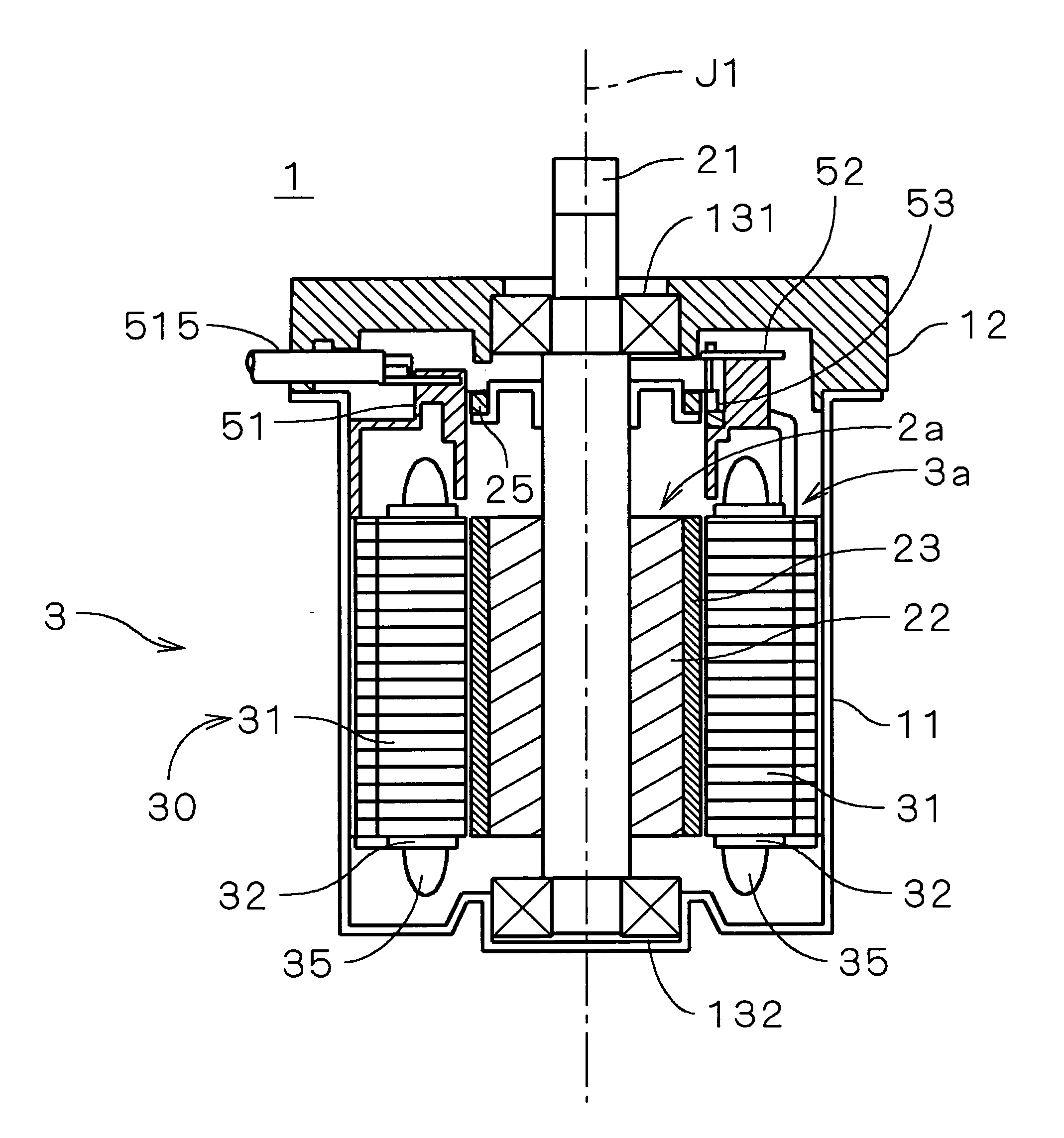
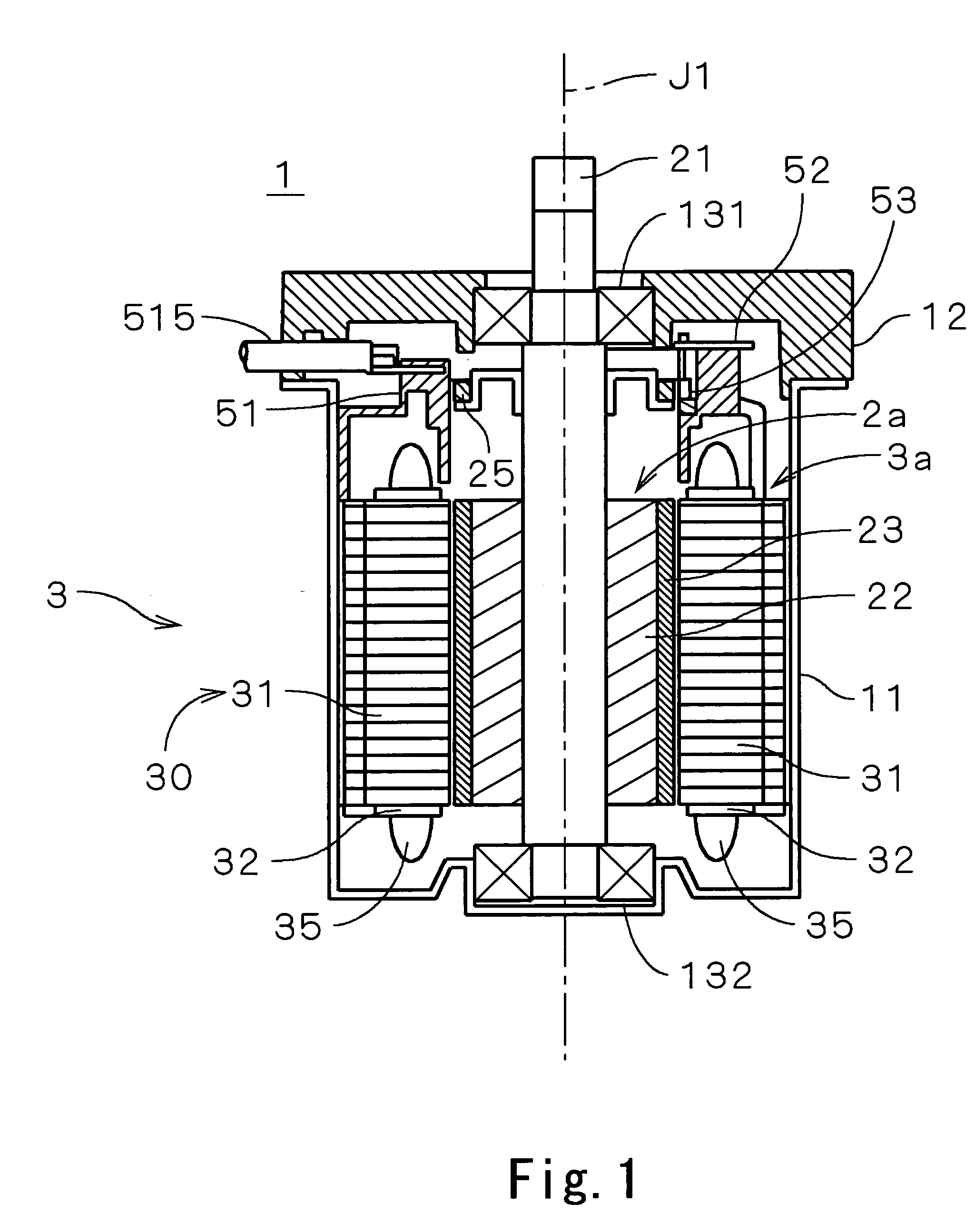
[0015]FIG. 1 is a vertical cross-sectional view showing an electric motor 1 in a preferred embodiment according to the invention. The motor 1 is a so-called brushless motor, which is used as, for example, a drive source for a power steering in an automobile. Incidentally, parallel hatch lines at fine portions in cross section will be omitted in FIG. 1.

[0016] In FIG. 1, the motor 1 is covered with a cylindrical housing 11, which is opened upward, and a cover 12, which is adapted to close the opening of the housing 11 and has an opening at the center thereof. Ball bearings 131 and 132 are fixed to the opening of the cover 12 and the bottom of the housing 11, respectively. The ball bearings 131 and 132 rotatably support a shaft 21.

[0017] To the shaft 21 is attached a columnar rotor yoke 22 inside of the housing 11. At an outer peripheral surface of the rotor yoke 22 is secured a field magnet 23 magnetized in a multi-polar manner. A sintered material containing neodymium, for example,...


PUM


Abstract

A bus bar secured to a stator in an electric motor in a preferred embodiment according to the invention includes four wiring boards, which are arranged perpendicularly to a center axis at intervals in a direction toward the center axis, and a resin portion for covering the surroundings of the four wiring boards by injection molding. Resin passing holes, through which a resin flows when the resin portion is molded, are formed at each of the wiring boards. When the bus bar is molded, the resin is injected into a resin molding die in a state in which the four wiring boards are supported by supporting pins disposed inside of the die. The resin flows to and fro between a space defined between the die and the wiring board and a space defined between the adjacent wiring boards.

Description

FIELD OF THE INVENTION [0001] The invention relates to an electric motor and a bus bar used in the electric motor. BACKGROUND OF THE INVENTION [0002] An electric motor in the prior art has been provided with a bus bar, in which wiring is configured for connecting a stator and an outside wiring to each other. Such a bus bar has included, for example, thin plate-like wiring members, which are formed into an annular shape on the axis of the motor and are laminated at predetermined intervals in an axial direction, and an insulating member, which is disposed between the plurality of wiring members so as to electrically insulate the wiring members from each other. [0003] As a bus bar fabricating method has been conventionally known a method for molding the plurality of wiring members with a resin by injecting the resin into a die, in which the wiring members are held at the predetermined intervals. In this case, the resin filled between the plurality of wiring members has been constituted...

Claims


Application Information

Patent Timeline
Patent Type & Authority Applications(United States)
IPC IPC(8): H05K1/00
CPCH02K3/522H02K5/225H02K15/0062H05K3/284H02K29/08H02K2203/09H05K1/144H02K15/12
Inventor MIGITA, TAKAYUKISUZUKI, HIROAKI
Owner NIDEC CORP
Why Eureka
Try Eureka