Eureka AIR delivers breakthrough ideas for toughest innovation challenges, trusted by R&D personnel around the world.

Ink jet head, connecting sheet, composite sheet, and method of manufacturing ink jet head and composite sheet

Inactive Publication Date: 2006-03-30
BROTHER KOGYO KK
View PDF3 Cites 0 Cited by
  • Summary
  • Abstract
  • Description
  • Claims
  • Application Information

AI Technical Summary

Benefits of technology

[0016] In this ink jet head, the connecting sheet is located between the main body and the wired sheet. As a result, dust, splashes of ink that have been splashed from the main body side, etc., are intercepted by the connecting sheet made of the insulating material. Ink splashes and dust are prevented from adhering to the wired sheet. By this means, t

Problems solved by technology

In this case, if ink splashes or dusts adhere to the wired sheet, there is a problem that there may be a short circuit between the output terminal and the adjacent signal line for another output terminal.
Or, there is a problem that there

Method used


Image

  • Ink jet head, connecting sheet, composite sheet, and method of manufacturing ink jet head and composite sheet
  • Ink jet head, connecting sheet, composite sheet, and method of manufacturing ink jet head and composite sheet
  • Ink jet head, connecting sheet, composite sheet, and method of manufacturing ink jet head and composite sheet

Examples


Example

DETAILED DESCRIPTION OF THE DRAWINGS

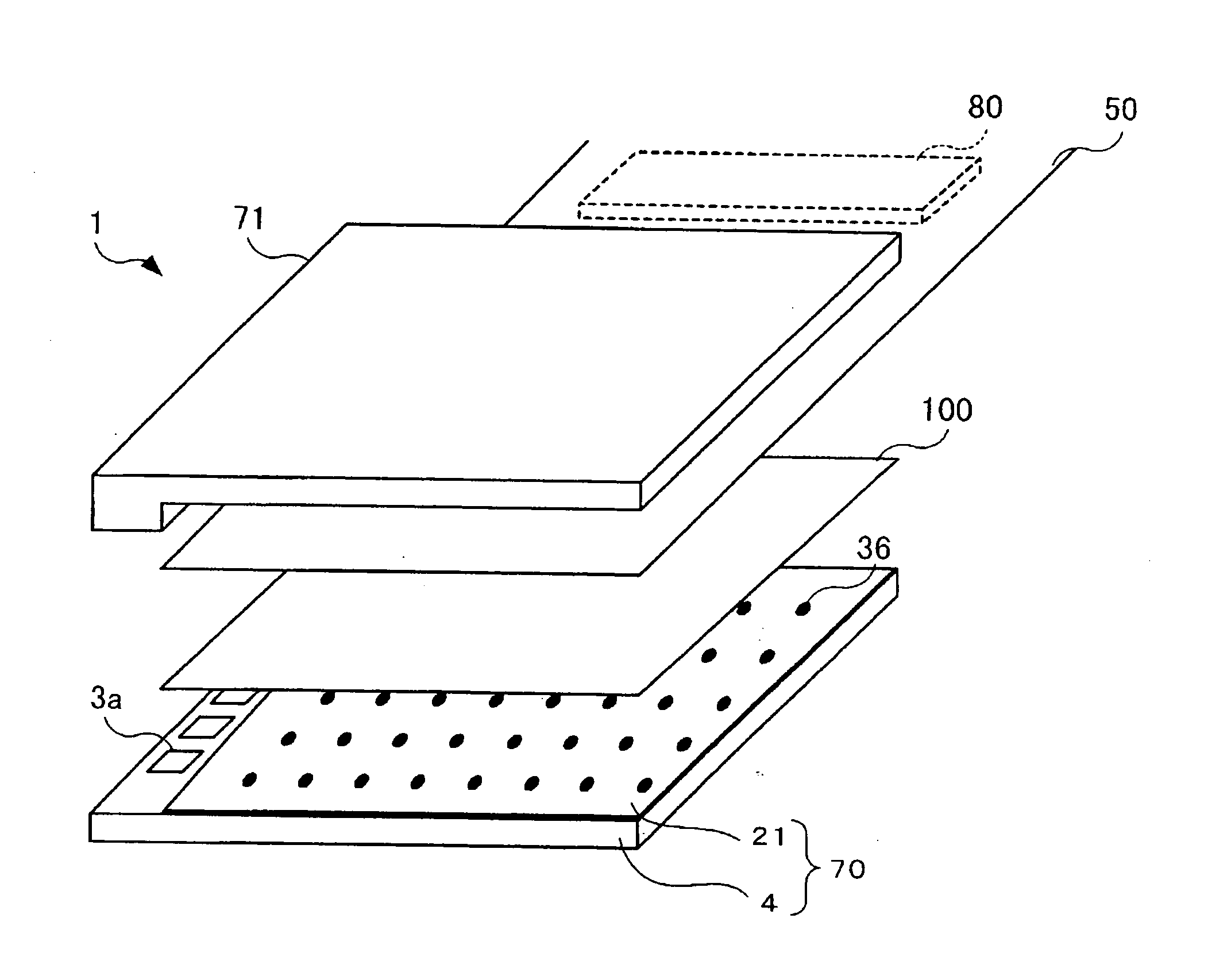
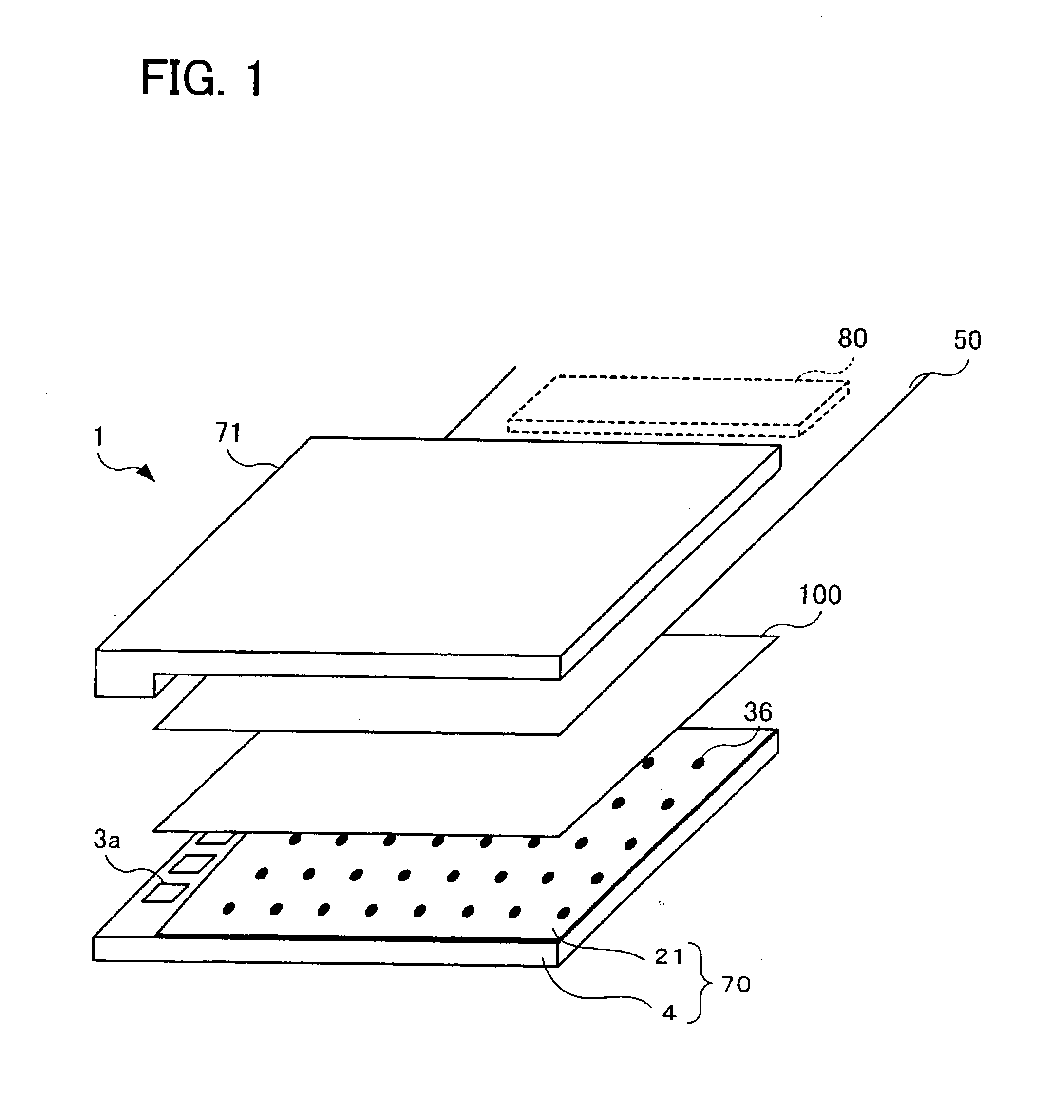
[0030] An ink jet head of an embodiment of the present invention will now be described. FIG. 1 shows an exploded perspective view of an ink jet head 1. As shown in FIG. 1, the ink jet head 1 is provided with a main body 70, an ink reservoir unit 71, a flexible printed wired sheet (FPC: Flexible Printed Circuit) 50, and a connecting sheet 100. The main body 70 has a rectangular flat bottom face for discharging ink onto a printing sheet. The ink reservoir unit 71 has an ink reservoir for storing ink to be supplied to the main body 70, and is connected with ink supply holes 3a formed in an upper face of the main body 70. The main body 70 is provided with an actuator unit 21 and an ink flow channel unit 4. The actuator unit 21 is disposed on an upper face of the ink flow channel unit 4. A driver IC 80 for driving the actuator unit 21 is fixed to the FPC 50. The FPC 50 is provided with a wired pattern for transmitting driving signals from the driver I...


PUM


Abstract

An ink jet head is provided with a main body, a wired sheet, and a connecting sheet. The main body is provided with a plurality of sets and each set includes an input terminal, an actuator, a pressure chamber and a nozzle. The wired sheet is provided with a plurality of sets and each set includes a signal line and an output terminal. The connecting sheet is provided with an insulating sheet and a plurality of sets and each set includes first terminal formed on a first face of the insulating sheet and a second terminal formed on a second face of the insulating sheet. In each set, the signal line, output terminal, second terminal, first terminal, input terminal and actuator are electrically connected. When a voltage is applied to the actuator in a selected set via the signal line, output terminal, second terminal, first terminal and input terminal, pressure is applied to ink within the pressure chamber in the selected set, and this ink jets from the nozzle in the selected set.

Description

CROSS-REFERENCE TO RELATED APPLICATION [0001] This application claims priority to Japanese Patent Application No. 2004-285865, filed on Sep. 30, 2004, the contents of which are hereby incorporated by reference into the present application. BACKGROUND OF THE INVENTION [0002] 1. Field of the Invention [0003] The present invention relates to an ink jet head to be mounted on an ink jet printer. Further, the present invention relates to a connecting sheet and a composite sheet to be used in the ink jet head. Moreover, the present invention relates to a method of manufacturing the ink jet head and the composite sheet. [0004] 2. Description of the Related Art [0005] Ink jet printers are well known. An ink jet printer is provided with an ink jet head that discharges ink. The ink jet head is provided with a plurality of nozzles, a plurality of pressure chambers, and a plurality of actuators. Each nozzle is communicated with a corresponding pressure chamber. Each pressure chamber is coupled w...

Claims


Application Information

Patent Timeline
IPC IPC(8): H01R4/24
CPCB41J2/14209B41J2002/14217B41J2002/14225B41J2002/14306B41J2002/14459B41J2002/14491H01R12/7076
Inventor ITO, KOJI
Owner BROTHER KOGYO KK
Why Eureka
Eureka Blog
Learn More