Shock absorbing and cooling structure

a technology of shock absorption and cooling structure, which is applied in the field of shock absorption structure, can solve the problems of limited success in the field of plastic structure impact absorption, foam does not allow heat to dissipate from the head or body, etc., and achieve the effect of dissipation of heat through the bas

Inactive Publication Date: 2006-04-06
PARADOX DESIGN SERVICES
View PDF12 Cites 68 Cited by
  • Summary
  • Abstract
  • Description
  • Claims
  • Application Information

AI Technical Summary

Benefits of technology

[0009] The present invention provides a shock absorbing structure comprising: a base manufactured from one of an expanded polystyrene or polypropylene foam, with the base having at least one recess formed therein and including an insert that is received within the recess. The insert includes a planar surface made of a flexible plastic material; a plurality of upstanding, hollow support members extending from the planar surface, the support members made of flexible plastic material; and at least one opening in each of the support members defining an air passage within the shock absorbing structure to allow air to flow through the support members. The insert allows heat to dissipate through the base while still providing impact absorption.

Problems solved by technology

These foams do not allow heat to dissipate from the head or body.
Heat stress has become a major detriment to exercise performance in athletes, industrial workers and military personnel, often leading to severe heat stroke causing death.
Some work has been done with plastic structures for impact absorption with limited success because of increased weight, increased thickness or high manufacturing costs.

Method used


Image

  • Shock absorbing and cooling structure
  • Shock absorbing and cooling structure
  • Shock absorbing and cooling structure

Examples


second embodiment

[0027]FIG. 5 illustrates the insert in accordance with the present invention, and being generally indicated at 118. Insert 118 comprises a foam member 119 and generally planar surface 120 adhesively connected together. Disposed on the planar surface 120 is a plurality of upstanding, hollow support members 122 extending outwardly from the planar surface 120. Foam member 119 is manufactured from the same material as the base 12. The planar surface 120 and convex sidewalls 124 are made of a suitable flexible plastic material such as a thermoplastic polymer like polyethylene. As such, the planar surface 120 and support members 122 are able to flex when a force is applied to them.

[0028] Support members 122 include sidewalls 124 that are preferably made of the same flexible plastic material as the planar surface 120, and are integral with the planar surface 120. Each of the support members 122 includes at least one opening 126 that define air passages within the insert 118 to allow air to...

third embodiment

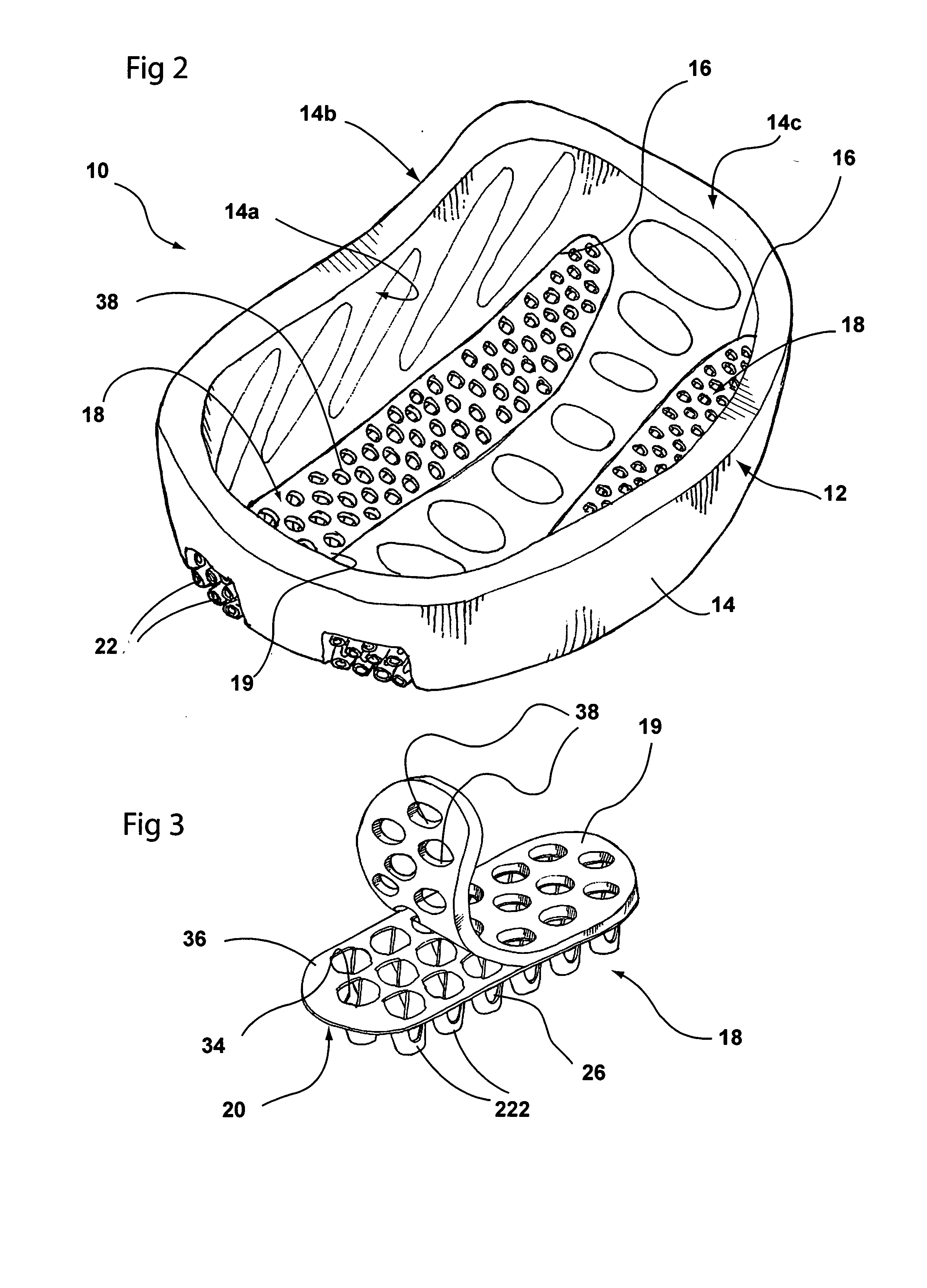
[0031]FIG. 6 illustrates the insert in accordance with the present invention and generally indicated at 218. Insert 218 comprises a foam member 219 and a generally planar surface 220 that are adhesively connected together. As before, foam member 219 is manufactured from a softer foam material than base 12. Disposed on the planar surface 220 is a plurality of upstanding, hollow support members 222 extending outwardly from the planar surface 220. The planar surface 220 are made of a suitable flexible plastic material such as a thermoplastic polymer like polyethylene. As such, the planar surface 220 and support members 222 are able to flex when a force is applied to them.

[0032] Support members 222 include sidewalls 224 that are preferably made of the same flexible plastic material as the planar surface 220, and are integral with the planar surface 220. Each of the support members 222 includes at least one opening 226 that define air passages within the insert 218 to allow air to flow t...


PUM


Abstract

A shock absorbing structure comprising a foam base defining a plurality of recesses, each of the recesses receiving shock absorbing inserts therein. Each insert includes a generally planar surface made of a foam layer and a flexible plastic layer and including a plurality of upstanding, hollow support members extending therefrom. The support members are made of flexible plastic material and have a plurality of openings therein which define air passages within the shock absorbing structure to allow air to flow therethrough. The shock absorbing structure may be used in helmets, shin pads, kneepads, elbow pads, shoulder pads, chest protectors, gloves, pants and footwear.

Description

CROSS REFERENCE TO RELATED APPLICATIONS [0001] This is a standard utility application claiming priority from U.S. Provisional Application Ser. No. 60 / 616,386, filed Oct. 6, 2004, the entire specification of which is incorporated herein by reference.BACKGROUND OF THE INVENTION [0002] 1. Technical Field [0003] The present invention relates to a shock absorbing structure. More particularly, the present invention relates to a shock absorber having a plurality of upstanding, hollow support members made of flexible plastic material. Specifically, the invention relates to a shock absorber that is formed into an insert and is then received within a recess formed in a base structure. [0004] 2. Background Information [0005] Helmets and other protective equipment typically use foam for impact absorption, specifically, expanded polystyrene (EPS), polyethylene (EPP) or thermoplastic blown foam. These foams do not allow heat to dissipate from the head or body. Heat stress has become a major detri...

Claims


Application Information

Patent Timeline
Patent Type & Authority Applications(United States)
IPC IPC(8): A42B3/00
CPCA41D31/0044A42B3/124A42B3/285A43B13/181A63B71/10A63B2225/66F16F9/0481
Inventor COPELAND, STEVEDICKIE, ROBERT G.
Owner PARADOX DESIGN SERVICES
Why Eureka
Try Eureka