Extendable and retractable support system

Inactive Publication Date: 2006-04-06
DESIGNED COMPONENTS
View PDF15 Cites 4 Cited by
  • Summary
  • Abstract
  • Description
  • Claims
  • Application Information

AI Technical Summary

Benefits of technology

[0005] According to various features, characteristics and embodiments of the present invention which will become apparent as the description the

Problems solved by technology

Prior art mechanisms used for raising and lowering collapsible tops on such structures are generally balky, hard to operate and maintain, and prone to failure.
For example, many lifting mechanisms rely on cranks and

Method used


Image

  • Extendable and retractable support system
  • Extendable and retractable support system
  • Extendable and retractable support system

Examples


Example

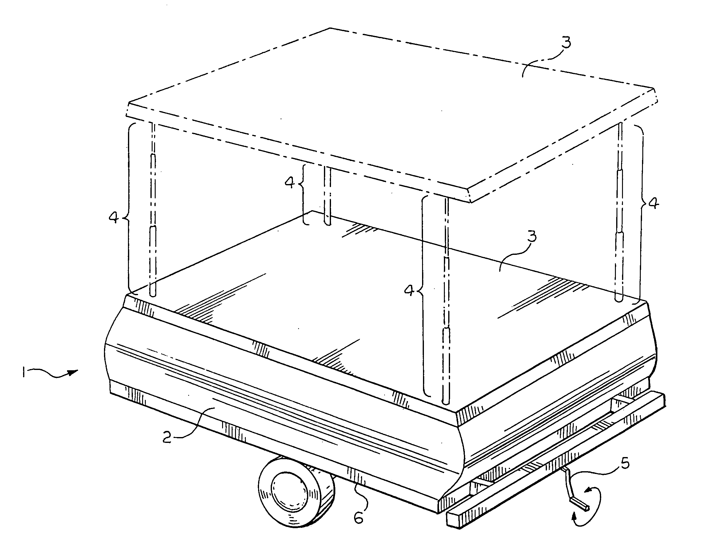
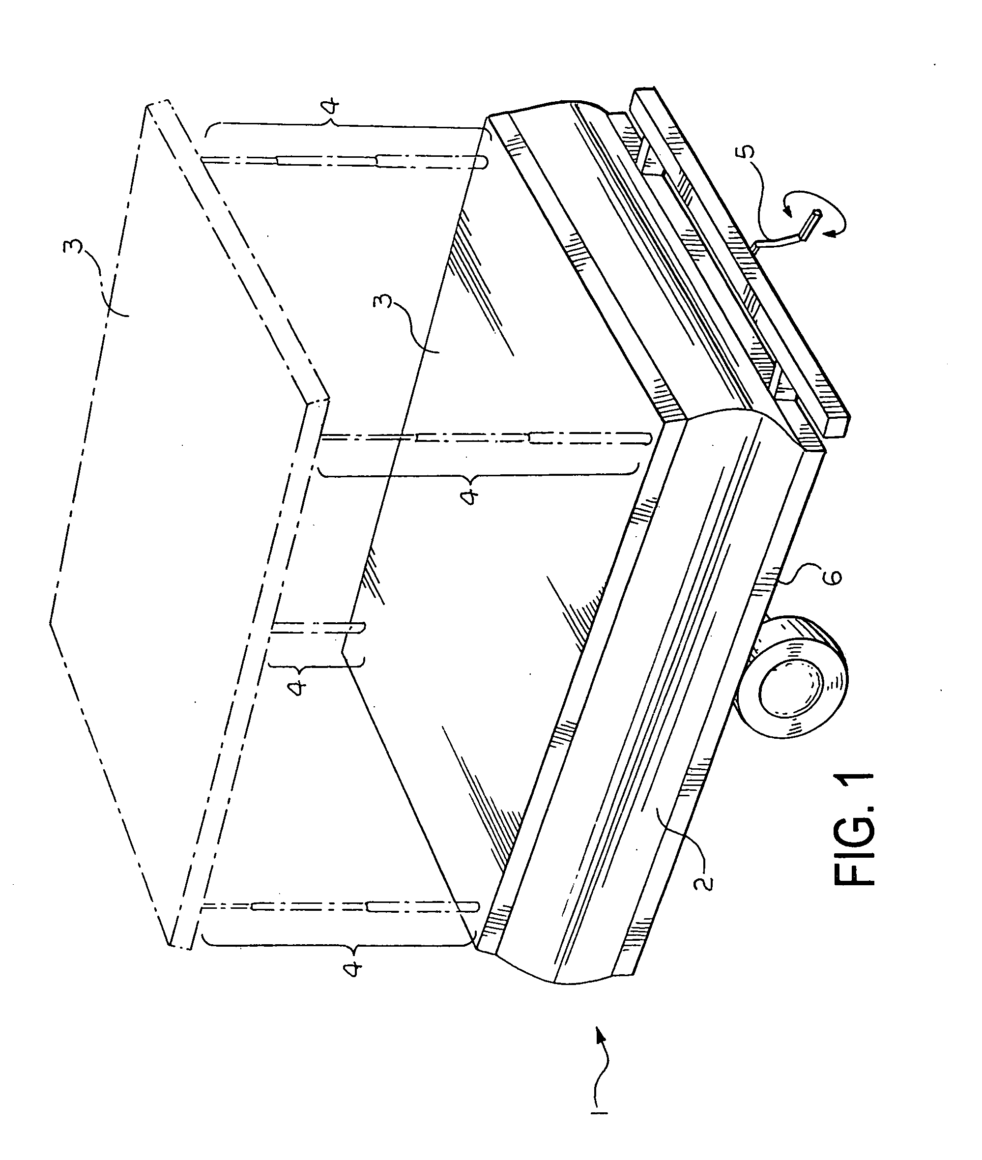
[0035] The present invention is directed to mechanisms which are used to raise and lower structures, including covers or tops of mobile or immobile dwellings. More particularly, the present invention is directed to extendable and retractable support systems that include telescopic assemblies which are used to raise and lower various structures, including covers or tops of mobile and immobile dwellings.

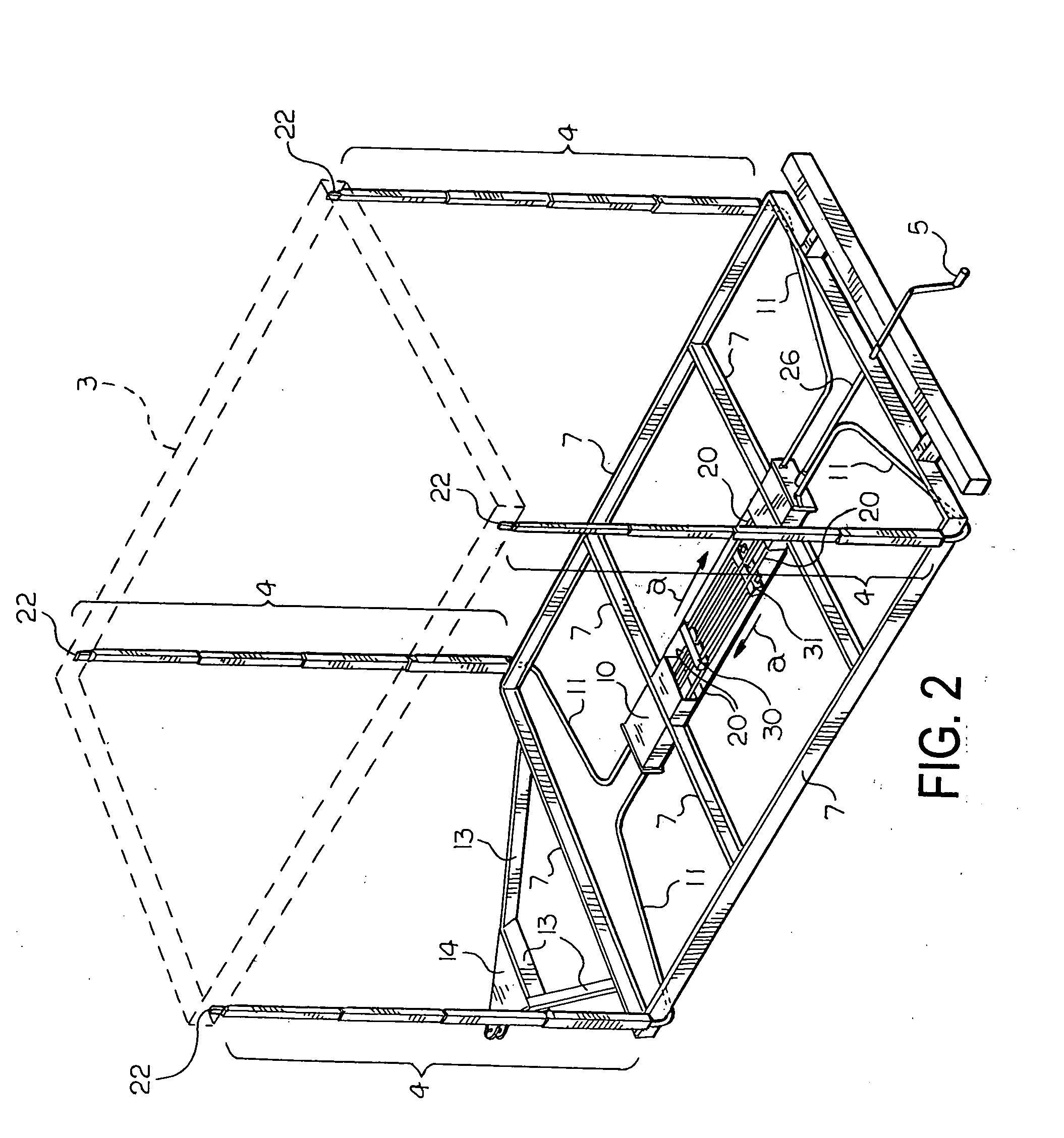
[0036] The extendable and retractable support systems of the present invention utilize mechanisms which push flexible rods such as extension springs through tubular guides. The distal ends of the flexible rods are coupled to or otherwise engage end portions of telescopic assemblies which are configured to support the tops, covers, caps, roofs, etc. of various structures including stationary and mobile structures such as campers, mobile homes, trailers, etc. as well as permanent and temporarily facilities, huts, dwellings, shelters, etc.

[0037] The flexible rods can be coupled to vario...


PUM


Abstract

An extendable and retractable support system for raising and lowering structures, including covers or tops of mobile and immobile dwellings which includes a plurality of telescopic assemblies. The telescopic assemblies include at least two tube members that are provided with enclosed sides and a centrally located internal channel structure that is parallel to and proximal to a center of the tube members, though which internal channel structures one of a plurality of spring elements extends. A mechanism extends and retracts the spring elements thereby causing the telescopic assemblies to extend and retract.

Description

TECHNICAL FIELD [0001] The present invention relates to mechanisms which are used to raise and lower structures, including covers or tops of mobile and immobile dwellings. More particularly, the present invention is directed to extendable and retractable support systems having telescopic assemblies which are used to raise and lower various structures, including covers or tops of mobile and immobile dwellings. BACKGROUND ART [0002] Towable tent campers and pop-up trailers having collapsible roofs are generally known in the art. Prior art mechanisms used for raising and lowering collapsible tops on such structures are generally balky, hard to operate and maintain, and prone to failure. For example, many lifting mechanisms rely on cranks and cables that are exposed to the elements, can accumulate dirt and debris, and can bind, slip and stretch. Mechanisms which are based upon gear driven assemblies are significantly heavier and more expensive to produce. [0003] The following U.S. Paten...

Claims


Application Information

Patent Timeline
IPC IPC(8): E04H6/00
CPCB60J7/1614B60P3/341
Inventor LAMBRIGHT, MICHAEL
Owner DESIGNED COMPONENTS
Why Eureka
Try Eureka