
Vehicle window regulator, and vehicle door structure comprising the vehicle window regulator

Inactive Publication Date: 2014-11-27
HI-LEX CORPORATION
View PDF15 Cites 0 Cited by
  • Summary
  • Abstract
  • Description
  • Claims
  • Application Information

AI Technical Summary

Benefits of technology

The present invention provides a window regulator that prevents the windowglass from rotating or tilting during raising and lowering, while still allowing it to move in the vehicle width directions. This is achieved through the use of a guide rail and a carrier plate that moves in the same direction as the windowglass. Additionally, a synchronization cable is used to connect the carrier plates and raise and lower them in a synchronized manner. The drive unit can be easily attached to the vehicle body, and the window regulator can be installed in a simple vehicle door structure. These technical effects provide a more stable and reliable window regulator that improves the performance of the vehicle's window system.

Problems solved by technology

As a result, the arrangement of a door pocket, a speaker, and the like is limited, and it is difficult to significantly change the layout of the door.

Method used


Image

  • Vehicle window regulator, and vehicle door structure comprising the vehicle window regulator
  • Vehicle window regulator, and vehicle door structure comprising the vehicle window regulator
  • Vehicle window regulator, and vehicle door structure comprising the vehicle window regulator

Examples


first embodiment

(4) Operation of First Embodiment

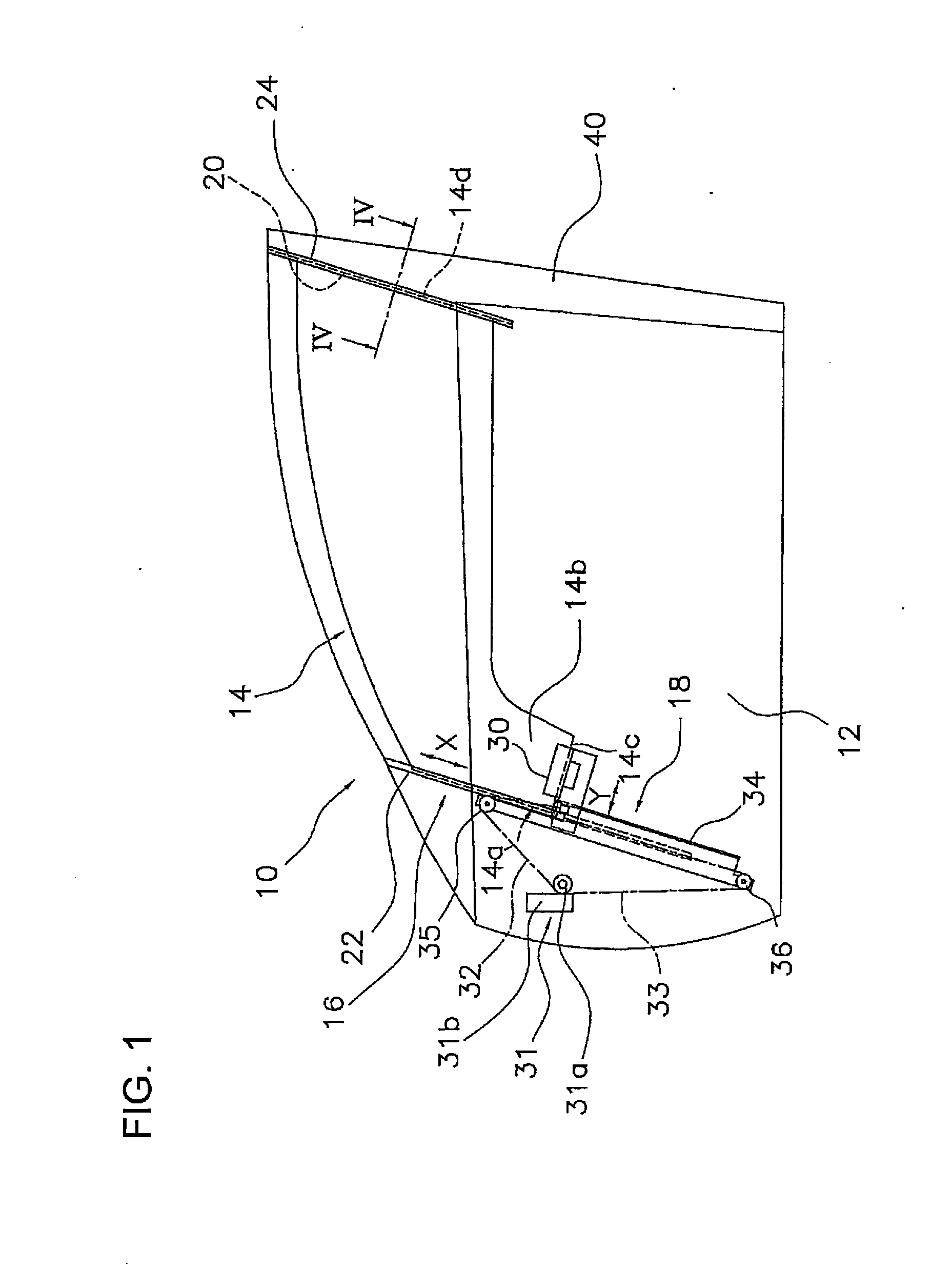
[0052]As shown in FIG. 5, in the door structure 10, when a lowering switch (not shown) provided to the door panel and the like is operated, the drum 31a of the drive unit 31 rotates in the lowering direction (e.g., clockwise in FIG. 5) indicated by an arrow R. Thereby, the lowering cable 33 is wound up onto the drum 31a and the raising cable 32 is paid out from the drum 31a, and thereby the windowglass 14 lowers to a lowering position, which is indicated in FIG. 5 by a chain double dashed line. At this time, if a lower end position of the first edge part 14a of the windowglass 14, namely, a point A2, is not constrained to the directions that intersect the movement directions of the windowglass 14 midway during the lowering indicated by the solid line, then there is a risk that the windowglass 14 will rotate, with an upper end position A1 of the first edge part 14a serving as a fulcrum, counterclockwise, with the vehicle width directions serving as an...

second embodiment

(7) Operation of Second Embodiment

[0065]In the door structure 110, when the lowering switch (not shown) provided to the door panel and the like is operated, the drum 31a of the drive unit 31 rotates in the lowering direction (e.g., clockwise in FIG. 6) indicated by the arrow R. Thereby, the lowering cable 33 is wound up onto the drum 31a and the raising cable 32 is paid out from the drum 31a, and thereby the windowglass 14 lowers toward the lowering position indicated by the chain double dashed line in FIG. 5. At this time, one end of the synchronization cable 139 lowers in accordance with the lowering of the carrier plate 130, and thereby the second carrier plate 137 lowers synchronized to the carrier plate 130.

[0066]In addition, when the raising switch is operated, the drum 31a of the drive unit 31 rotates in a raising direction (e.g., counterclockwise in FIG. 6), which is the reverse direction of the arrow R. Thereby, the raising cable 32 is wound up onto the drum 31a and the low...

third embodiment

[0069]In a third embodiment, as shown in FIG. 8, the mounting mode of a drive unit 231 of a window regulator 218 differs from that of the first embodiment and that of the second embodiment. Other aspects of the configuration are the same as those of the first embodiment, and explanations thereof are therefore omitted.

(8) Drive Unit

[0070]The drive unit 231 is provided to a bracket 241, which is provided between an upper end and a lower end of the guide rail 34. The drive unit 231 comprises: the drum 31a, whereto the other end of the raising cable 32 and the other end of the lowering cable 33 are coupled; and the drive unit 31b, which comprises the reduction gear and the motor and rotatably drives the drum 31a.

[0071]As mentioned above, the drive unit (e.g., the drive unit 231) is attached to the bracket (e.g., the bracket 241) provided between the upper end and the lower end of the guide rail (e.g., the guide rail 34). Accordingly, the assembly cost can be reduced by virtue of the at...


PUM


Abstract

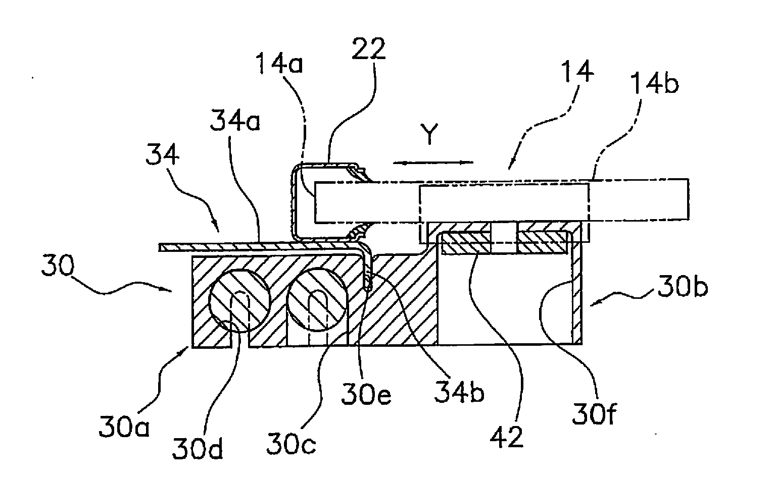
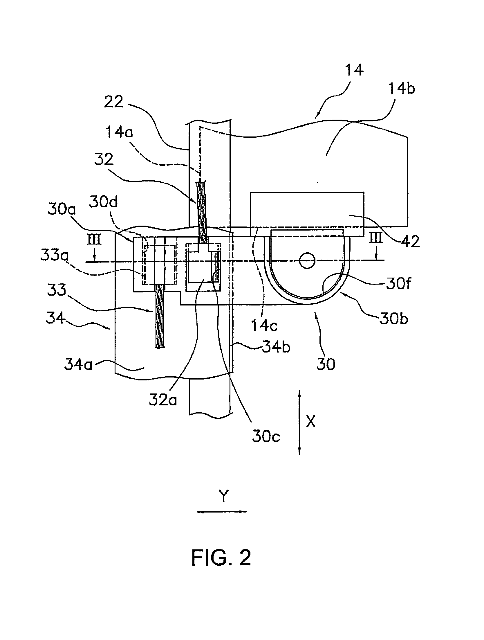
A window regulator comprises a carrier plate, a drive unit, a raising cable, a lowering cable, and a guide rail. The carrier plate is attached to a lower part on a first edge part side of the windowglass. The drive unit is capable of raising and lowering the windowglass via the carrier plate. The drive unit and the carrier plate are coupled by the raising cable and the lowering cable. The guide rail mates with the carrier plate so as to guide the carrier plate and constrain the operation of the windowglass to directions that intersect movement directions of the carrier plate.

Description

TECHNICAL FIELD[0001]The present invention relates to a vehicle window regulator, which raises and lowers a windowglass of a vehicle, and a vehicle door structure that comprises the vehicle window regulator.BACKGROUND ART[0002]In the conventional art, a window regulator is known that, in order to support a windowglass, connects two fixed carrier plates, which are spaced apart by a spacing in the vehicle front-rear directions, to a lower end of the windowglass, such that the windowglass is supported from both sides or in the vicinity of its center, and raises and lowers the windowglass (e.g., refer to Patent Document 1).[0003]Consequently, in the window regulator of Patent Document 1, a drive unit (i.e., a motor) that raises and lowers the windowglass must be disposed in the vicinity of the center of a door panel. As a result, the arrangement of a door pocket, a speaker, and the like is limited, and it is difficult to significantly change the layout of the door.CITATION LISTPatent Li...

Claims


Application Information

Patent Timeline
IPC IPC(8): B60J1/17E05F11/48
CPCB60J1/17E05Y2900/50E05F11/486E05F11/382E05F11/488E05Y2201/612E05Y2900/55
Inventor YOSHIMURA, TATSUOHOSOI, HIDEYA
Owner HI-LEX CORPORATION
Learn More