Floating boat lifting apparatus for raising or lowering the boat from or onto the water

Inactive Publication Date: 2017-07-13
KSB&SUNGPOONG CO LTD
View PDF3 Cites 1 Cited by
  • Summary
  • Abstract
  • Description
  • Claims
  • Application Information

AI Technical Summary

Benefits of technology

[0058]The lower parts of the lifting assemblies of the boat lifting apparatuses according to the present invention are not submerged when the watercraft is completely raised above the water, the places of the floats on which the load are focused are not subject to wear and thus the durability of the apparatus can be increased, and the movement of the floats is natural and soft while they rotate to raise or lower the watercraft.
[0059]Further, in some floats of the boat lifting apparatuses according to the present inv

Problems solved by technology

Generally, when a watercraft is moored at a berthage, a hull of a watercraft may be subjected to physical damage by wave activity resulting from the wakes of passing watercraft.
Such marine life attached to the hull of the watercraft lower the sailing speed of the watercraft on account of friction between the hull of the watercraft and the water.
This may cause a significant problem because more than two times of cost of fuel may be required.
However, because most antifouling paint is toxic and causes seawater pollution, its use on the hull of the watercraft is regulated by International Ma

Method used


Image

  • Floating boat lifting apparatus for raising or lowering the boat from or onto the water
  • Floating boat lifting apparatus for raising or lowering the boat from or onto the water
  • Floating boat lifting apparatus for raising or lowering the boat from or onto the water

Examples


Example

[0113]The first embodiment of the present invention is explained as below.

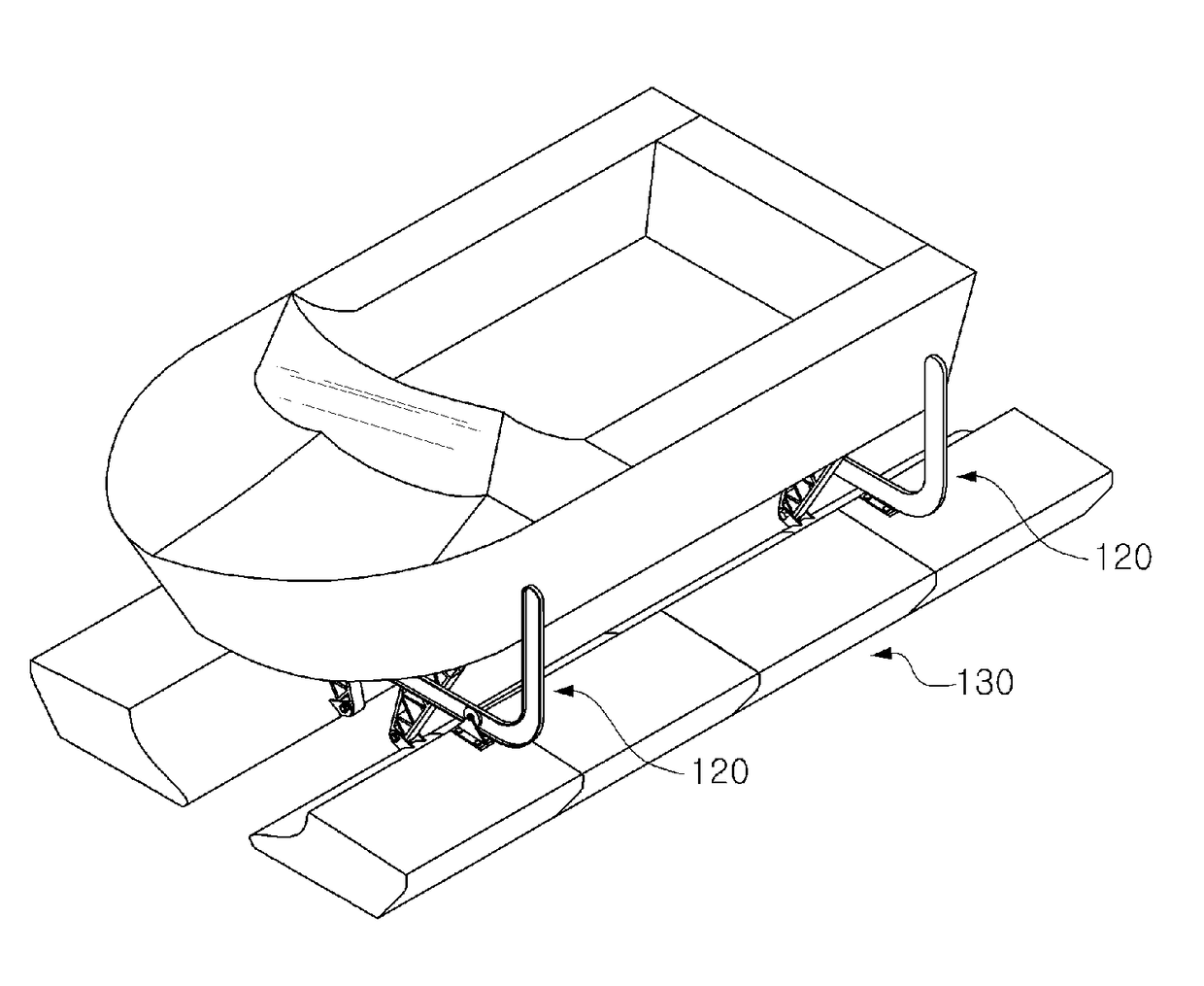
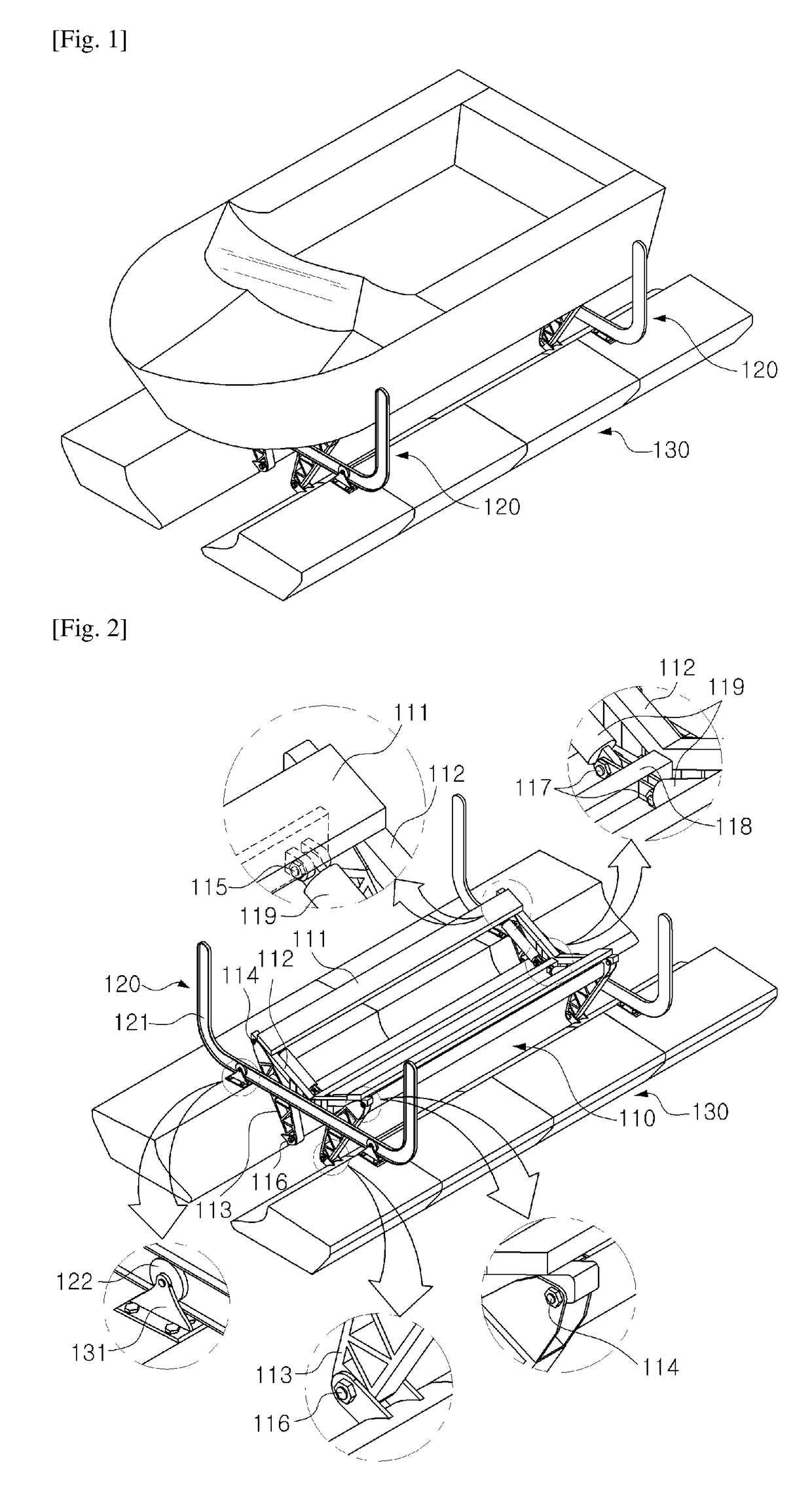
[0114]FIG. 1 is a perspective view of the floating boat lifting apparatus for raising or lowering the boat from or onto the water according to the first embodiment of the present invention, wherein the watercraft is loaded.

[0115]FIG. 2 is a perspective view of the floating boat lifting apparatus according to the first embodiment of the present invention, wherein the main parts of the apparatus are enlarged. A floating boat lifting apparatus according to the first embodiment of the present invention mainly comprises the lifting assembly (110) positioned between a pair of parallel floats (130) to receive the watercraft, a pair of U-typed guide structures (120) to guide the floats (130) below or above the water (34), and a pair of parallel floats (130) longitudinally extended.

[0116]The lifting assembly (110) is inwardly and downwardly configured to receive or support the watercraft and includes a pair of bunks (1...

Example

[0143]The greatest feature of the boat lifting apparatus according to the second embodiment of the present invention is that the lifting assembly (210) is always above the water except for a few minutes when a part of the lifting assembly (210) is submerged at the time of lowering the watercraft. Accordingly, the apparatus except for the floats (230) and a part of the lifting assembly (210) is almost always above the water, and thus the corrosion of the apparatus is delayed, and the durability of the apparatus can be increased.

[0144]Referring to FIG. 13 to FIG. 18, the worm gear-operated floating boat lifting apparatus according to the third embodiment of the present invention is explained in detail as below.

[0145]FIG. 13 shows that the watercraft is loaded on the worm gear-operated floating boat lifting apparatus according to the third embodiment of the present invention and raised from the waterline (34).

[0146]FIG. 14 is a perspective view of the worm gear-operated floating boat l...

Example

[0151]The worm gear-operated floating boat lifting apparatus according to the third embodiment of the present invention may further comprise a locking means to provide against a disorder of the worm gear. The locking means comprises the third support (332) of the U-typed frame (311), the fourth support (331) attached to the top of the float (330), the hole (329) (refer to FIG. 15) formed at the tip of the third support (332), and the solenoid (333) wherein the solenoid pin locks or unlocks the third and fourth supports (331,332).

[0152]FIG. 15 shows a state that the watercraft is submerged and the floats (330) are fully raised from the waterline (34). Prior to the raising operation of the worm gear-operated floating boat lifting apparatus, the electric power connected to the solenoid (333) is turned on to release the solenoid pin from the third support (332) and the fourth support (331), and then the electric power (not shown) connected to the motor (326) is turned on. The left worm ...


PUM


Abstract

The present invention relates to a boat lift device for lifting a ship, such as a motorboat, a utility boat, a prefabricated rubber boat, a shipping boat, a cruise yacht, or a dinghy yacht, above the surface or for floating the same on the surface and, more particularly, to a boat lift device operated by a hydraulic cylinder, air, water pressure, a worm gear, or a rotor. A device for floating a ship or lifting an immersed boat according to the present invention is configured such that, when the ship is fully lifted above the surface, the lower portion of a lifting assembly is not immersed below the surface, and load transfer portions of buoyancy tanks are not abraded, thereby ensuring excellent durability and natural, smooth operation of the buoyancy tanks. In addition, the device for floating a ship or lifting an immersed boat according to the present invention has a reduced radius of rotation of the buoyancy tanks, or the lifting assembly ascends/descends vertically in an elevator type while the buoyancy tanks are floating on water, thereby improving the space usability of the place at which the boat lift device is installed, and making the locking means and the lifting assembly simple. Furthermore, the device for floating a ship or lifting an immersed boat according to the present invention guarantees that, even when a ship is lifted or lowered on a predetermined rock face or at a fixed marina mooring facility, the interval between the buoyancy tanks does not increase at all, thereby substantially improving space usability.

Description

TECHNICAL FIELD[0001]The present invention relates to a boat lifting apparatus for raising or lowering a watercraft such as motor boat, utility boat, self-assembly rubber boat, fishing craft, cruise yacht, and dinghy yacht from or onto the water.BACKGROUND ART[0002]Generally, when a watercraft is moored at a berthage, a hull of a watercraft may be subjected to physical damage by wave activity resulting from the wakes of passing watercraft.[0003]Further, when the watercraft is sailed or submerged in water, particularly seawater for long period, about 600 types of marine life including shellfish such as barnacles, mussels and oysters are attached to the submerged hull of the watercraft. Such marine life attached to the hull of the watercraft lower the sailing speed of the watercraft on account of friction between the hull of the watercraft and the water. This may cause a significant problem because more than two times of cost of fuel may be required. In order to protect the hull of th...

Claims


Application Information

Patent Timeline
IPC IPC(8): B63C1/02B63C3/06B63C3/12B63B35/00
CPCB63C1/02B63C3/12B63C3/06B63B35/00B63C1/04B63B34/05
Inventor CHOI, IM CHEOLJEON, GYEONG HWA
Owner KSB&SUNGPOONG CO LTD
Why Eureka
Try Eureka