Plasma air dust collector

a dust collector and plasma technology, applied in the field of plasma air dust collectors, can solve the problems of inability to improve the dust collection efficiency and the following problems of the conventional plasma air dust collector, and achieve the effects of improving dust collection efficiency, increasing the dust collection surface, and reducing the total volum

Active Publication Date: 2006-04-06
LG ELECTRONICS INC
View PDF8 Cites 38 Cited by
  • Summary
  • Abstract
  • Description
  • Claims
  • Application Information

AI Technical Summary

Benefits of technology

[0014] In order to solve the above-described problems, it is an object of the present invention to provide a compact plasma air dust collector by reducing a total volume.
[0015] It is another object of the present invention to provide a plasma air dust collector capable of improving dust collecting efficiency by increasing a dust collecting surface of a dust collecting electrode.

Problems solved by technology

However, in the compact structure or high performance aspect, the conventional plasma air dust collector has following problems.
Second, because the dust collecting electrode 16 is formed as a plate shape and dust collecting is performed on only the internal surface thereof, dust collecting efficiency can not be improved.

Method used


Image

  • Plasma air dust collector
  • Plasma air dust collector
  • Plasma air dust collector

Examples


Embodiment Construction

[0038] Hereinafter, the preferred embodiments of the present invention will be described with reference to accompanying drawings.

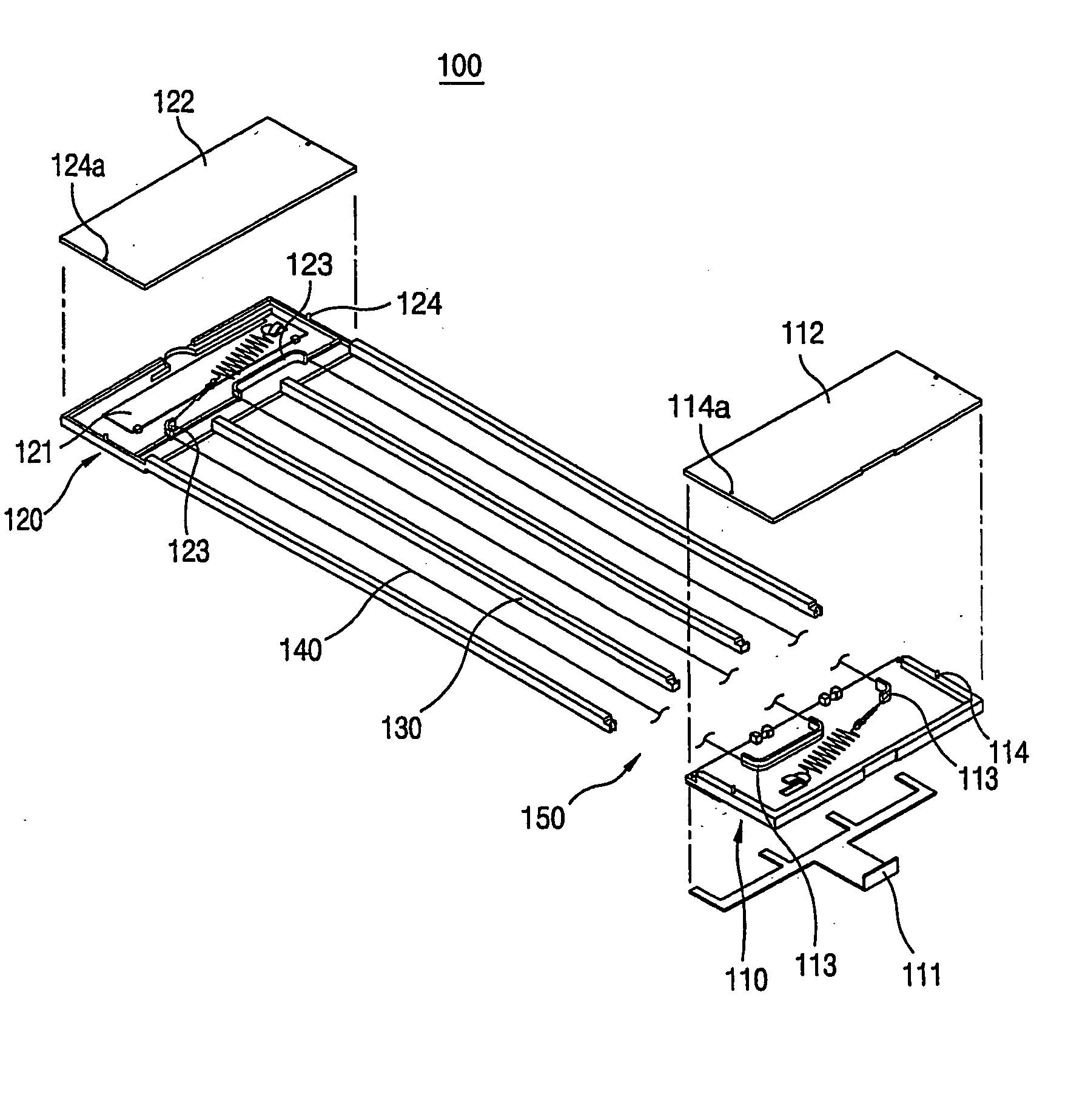
[0039]FIG. 6 is an exploded-perspective view illustrating a plasma air dust collector in accordance with the present invention; FIG. 7 is a combined-perspective view illustrating the plasma air dust collector in accordance with the present invention; FIG. 8 is a sectional view taken along a line B-B in FIG. 7; FIG. 9 is a sectional view taken along a line C-C in FIG. 7; FIG. 10 is a longitudinal-sectional view illustrating another embodiment of a discharge electrode in the plasma air dust collector in accordance with the present invention; and FIG. 11 is an exploded-perspective view illustrating a major part in FIG. 6.

[0040] As depicted in FIGS. 6˜11, the plasma air dust collector 100 in accordance with the present invention includes a first electrode fixing unit 110 having a dust collecting electrode power terminal 111; a second electrode fixing unit 12...


PUM


Abstract

In a plasma air dust collector, the plasma air dust collector includes a first electrode fixing unit and a second electrode fixing unit respectively having a power terminal; at least two dust collecting electrodes; a discharge electrode arranged between the dust collecting electrodes; a terminal protrusion formed at the bottom end of each dust collecting electrode in the length direction; a terminal protrusion insertion hole formed at a side of the first electrode fixing unit; a combining protrusion formed at a side of the first electrode fixing unit and the second electrode fixing unit; and a combining groove formed at the both ends of each dust collecting electrode.

Description

TECHNICAL FIELD [0001] The present invention relates to a plasma air dust collector, and in particular to a plasma air dust collector installed inside an air conditioner to purify indoor air by collecting dust in air sucked into the air conditioner. BACKGROUND ART [0002] In general, an air conditioner is divided into an indoor unit and an outdoor unit, the indoor unit is installed indoors, the outdoor unit is installed outdoors, and the indoor unit and the outdoor unit are connected with each other through pipes and wiring. [0003]FIG. 1 is a longitudinal-sectional view illustrating an indoor unit of a general panel type air conditioner. [0004] As depicted in FIG. 1, the indoor unit of the general panel type air conditioner includes a casing 3 having a suction hole 1 at the top and a discharge hole 2 at the bottom; a heat exchanger 4 installed in the casing 3; a fan 5 installed at the rear of the heat exchanger 4; and a plasma air dust collector 10 installed at the front of the heat ...

Claims


Application Information

Patent Timeline
Patent Type & Authority Applications(United States)
IPC IPC(8): B03C3/40B03C3/32F24F8/10B03C3/47F24F1/00
CPCB03C3/47F24F1/0007F24F3/166F24F2001/0037F24F1/0047F24F8/192Y02A50/20F24F8/10F24F1/0076B03C3/32
Inventor HONG, YOUNG-KILEE, SUNG-HWAPARK, JEONG-HO
Owner LG ELECTRONICS INC
Why Eureka
Try Eureka