Sheave for elevator

a technology for elevators and sheaves, applied in mine lifts, elevators, transportation and packaging, etc., can solve the problems of increased friction resistance between ropes and sheaves, and high fatigue of ropes, so as to reduce rope fatigue, prolong the life of ropes, and restrict the deterioration of specific parts of ropes.

Inactive Publication Date: 2006-04-06
TOSHIBA ELEVATOR KK
View PDF53 Cites 20 Cited by
  • Summary
  • Abstract
  • Description
  • Claims
  • Application Information

AI Technical Summary

Benefits of technology

[0012] An object of the present invention is to provide a sheave for elevator, capable of reducing fatigue of ropes, restricting deterioration of specific portions of the ropes and extending the lifetime of the ropes.

Problems solved by technology

In the above-described 2-to-1 roping type elevator, however, there is a problem that since the rope is wound round many sheaves the rope has much fatigue.
Thus, frictional resistance between the rope and the sheaves is increased by a force of a direction of releasing the twist and specific portions of the rope are remarkably deteriorated.

Method used


Image

  • Sheave for elevator
  • Sheave for elevator
  • Sheave for elevator

Examples


first embodiment

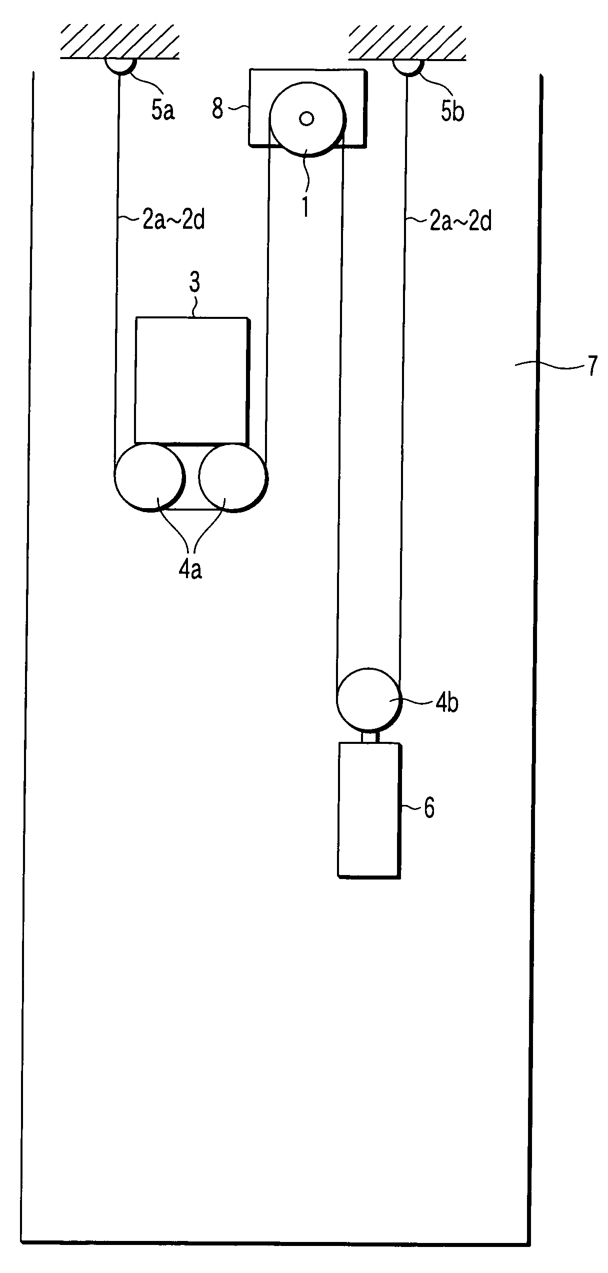
[0021]FIG. 1 is an illustration of a 2-to-1 roping type elevator employing a sheave according to a first embodiment of the present invention.

[0022] The elevator is machine room-less and a traction machine 8 is provided in a hoistway 7. A main sheave 1 is coupled to a drive shaft of the traction machine 8. A plurality of (four, in this embodiment) ropes 2a to 2d are wound round an outer peripheral surface of the main sheave 1.

[0023] One-side ends of the ropes 2a to 2d are fixed to a rope hitch 5a via sheaves 4a provided on a lower portion of a car 3. Other-side ends of the ropes 2a to 2d are fixed to a rope hitch 5b via a sheave 4b provided on a counter weight 6.

[0024] The sheaves 4a restrict passage of the ropes 2a to 2d between the main sheave 1 and the rope hitch 5a and support the car 3. The sheave 4b restrict passage of the ropes 2a to 2d between the main sheave 1 and the rope hitch 5b and support the counter weight 6. The rope hitches 5a and 5b are provided on a top portion ...

second embodiment

[0045] Next, a second embodiment of the present invention will be described.

[0046]FIG. 5 is a partially sectional view showing a structure of a sheave according to the second embodiment of the present invention. Similarly to the sheave 10, a sheave 20 shown in FIG. 5 corresponds to the sheaves 4a and 4b in FIG. 1.

[0047] The sheave 20 comprises a shaft 21 attached to the car 3 or the counter weight 6, and rope-corresponding sheaves 22a to 22d corresponding to a plurality of (four, in this embodiment) ropes, which are arranged side by side with an equal interval along an axial direction of the shaft 21.

[0048] The number of rope-corresponding sheaves 22 a to 22d is equal to the number of the ropes 2a to 2d wound round the main sheave 1 shown in FIG. 1. The sheaves 22a to 22d are provided to rotate about the shaft 21 independently of each other. A plurality of grooves 23a to 23d in which the ropes 2a to 2d are wound are formed on outer peripheral surfaces of the rope-corresponding sh...


PUM


Abstract

Coating layers of low-friction coating materials helping a rotating action generated on ropes are provided on surfaces of grooves formed on an outer peripheral surface of a base of a sheave. Thus, difference in tension between the ropes can be solved, generation of twist on the ropes can be prevented, and deterioration of portions of the ropes which are in contact with the sheave can be prevented to extend the lifetime of the ropes.

Description

CROSS-REFERENCE TO RELATED APPLICATIONS [0001] This is a Continuation Application of PCT Application No. PCT / JP2004 / 008672, filed Jun. 15, 2004, which was published under PCT Article 21(2) in English. [0002] This application is based upon and claims the benefit of priority from prior Japanese Patent Application No. 2003-173582, filed Jun. 18, 2003, the entire contents of which are incorporated herein by reference.BACKGROUND OF THE INVENTION [0003] 1. Field of the Invention [0004] This invention relates to a sheave suitable for a 2-to-1 roping type machine room-less elevator allowing a traction machine to be provided in a hoistway. [0005] 2. Description of the Related Art [0006] 2-to-1 roping type elevators are installed in residential buildings, mid-rise office buildings and the like. The 2-to-1 roping type indicates a method of hanging a car and a counter weight without directly connecting a rope to the car or the counter weight. On the other hand, a 1-to-1 roping type indicates a ...

Claims


Application Information

Patent Timeline
Patent Type & Authority Applications(United States)
IPC IPC(8): B66B5/00B66B11/08B66B15/04
CPCB66B15/04B66B11/08B66B11/00B66B11/04
Inventor OSADA, AKIRAHIRUMA, NOBORU
Owner TOSHIBA ELEVATOR KK
Why Eureka
Try Eureka