Container cartridge for beverage dispenser and support structure thereof

a beverage dispenser and container technology, applied in the direction of pliable tubular containers, packaging goods types, liquid handling, etc., can solve the problems of cartridges that cannot be efficiently transported for recycling or disposal, remain bulky after use, etc., and achieve the effect of preventing deformation of the container cartridge during us

Inactive Publication Date: 2006-04-06
COSMO LIFE
View PDF17 Cites 18 Cited by
  • Summary
  • Abstract
  • Description
  • Claims
  • Application Information

AI Technical Summary

Benefits of technology

[0007] Since at least the side wall is flexible, the used, empty container cartridge can be efficiently transported by collapsing it.
[0008] The bottom wall, side wall and top wall, including the spout, are preferably integrally formed of a common thermoplastic synthetic resin, the side wall being sufficiently thin so as to have flexibility. Such a container cartridge can be efficiently manufactured at a low cost.
[0011] The spout is preferably provided with an engaging portion for engaging a support member such that the container cartridge is hung from the support member with the spout facing upward. With this arrangement, the engaging portion stably keeps the spout in position while the side wall expands spontaneously under the weight of the beverage introduced into the container cartridge through the spout.
[0013] Preferably, the bottom wall has rigidity, and is provided with a flange or a plurality of claws protruding outwardly of the side wall. The flange or the plurality of claws are brought into engagement with the top of a frame member surrounding the container cartridge to prevent the container cartridge from collapsing during use.
[0014] The present invention also provides a support structure for supporting the container cartridge for use with a beverage dispenser, wherein the support structure comprises a frame member supported on the beverage dispenser and surrounding the container cartridge such that the flange or the plurality of claws protruding from the edge of the bottom wall of the container cartridge are adapted to engage the top end of the support structure when the container cartridge is set in the dispenser. The support structure prevents deformation of the container cartridge during use.

Problems solved by technology

Since such a container cartridge has rigidity in its entirety, it remains bulky after use.
Thus, such a cartridge cannot be efficiently transported for recycling or disposal.

Method used


Image

  • Container cartridge for beverage dispenser and support structure thereof
  • Container cartridge for beverage dispenser and support structure thereof
  • Container cartridge for beverage dispenser and support structure thereof

Examples


first embodiment

[0034]FIG. 6 shows a modification of the container cartridge 1 of the first embodiment, in which the flange 8 is replaced with a plurality of claws 8a protruding outwardly from the edge of the bottom wall 2. Like the flange 8, the claws 8a are adapted to engage the top end of the support structure 15.

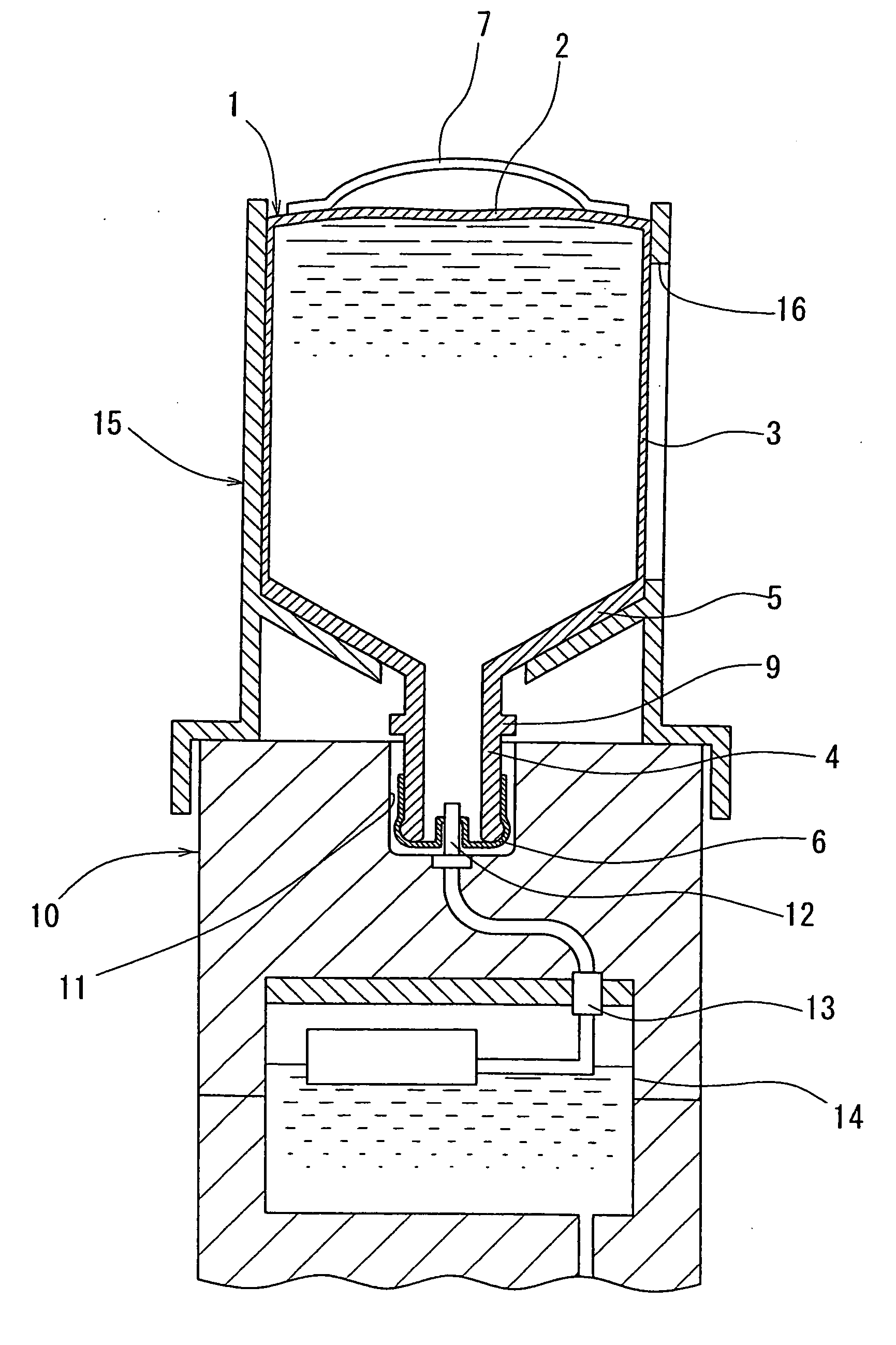
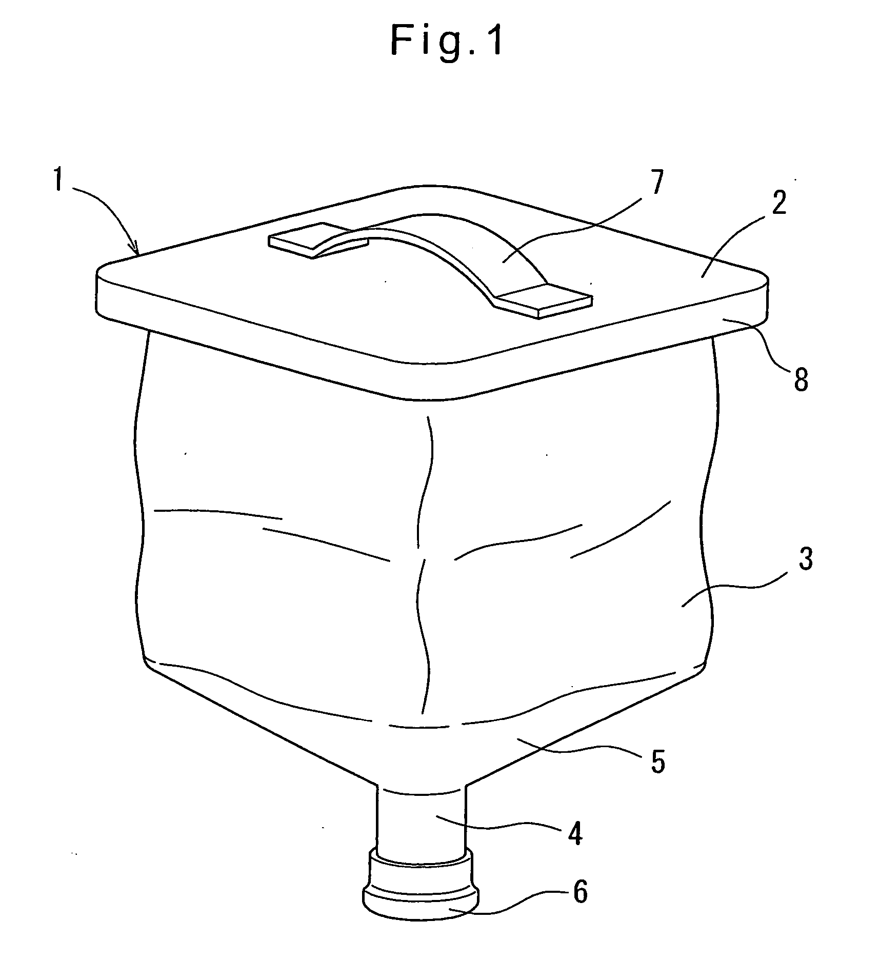
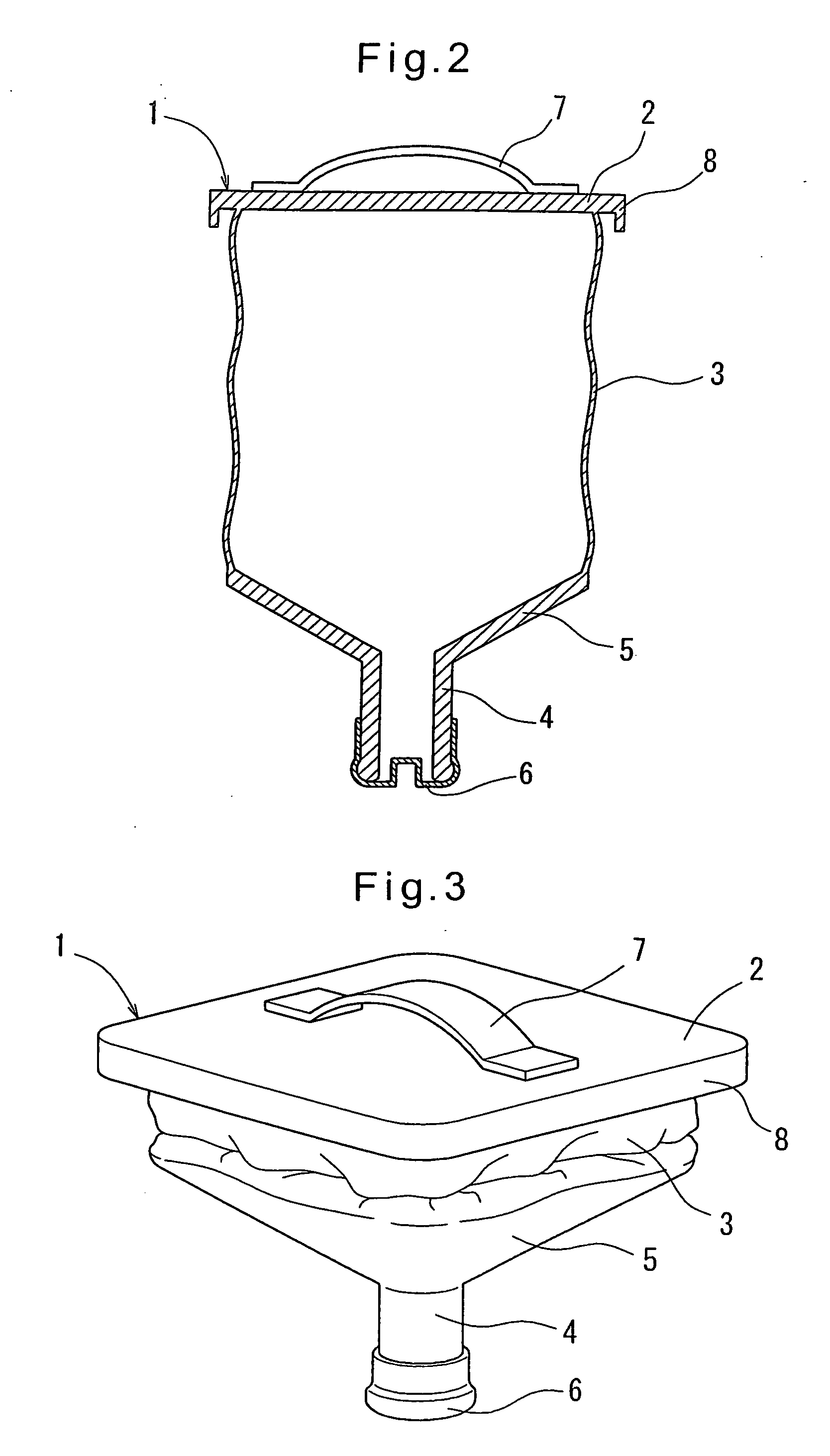
[0035] FIGS. 7 to 11 show the second embodiment. As shown in FIGS. 7A and 7B, the container cartridge 1 of the second embodiment is basically of the same structure as the container cartridge 1 of the first embodiment, and differs therefrom only in that the bottom wall 2 is thin, and in that a flange 9 is provided around the spout 4.

[0036] As shown in FIG. 8, beverage is poured into the container cartridge 1 through a hose 20 with the flange 9 supported on a bifurcated engaging member 21b secured to a rod 21a of a support 21 such that the container cartridge 1 is hung from the bifurcated member 21b. With this arrangement, the spout 4 is stably fixed in position so as to be always locate...

second embodiment

[0039]FIG. 10 shows a modification of the second embodiment, in which instead of the flange 9, a groove 9a is formed around the spout 4. The groove 9a is defined by an upper wall perpendicular to the spout 4 and a radially outwardly inclined lower wall. In this arrangement, beverage is poured into the container cartridge 1 through a hose 20 with the bifurcated engaging member 21b of the support 21 inserted in the groove 9a from both sides of the spout 5 such that the container cartridge 1 is hung from the bifurcated member 21b. With this arrangement, too, the spout 4 is stably fixed in position so as to be always located right under the outlet port of the hose 20.

[0040] The container cartridge of either embodiment is a bottle having a square cross-section, and made of a polyethylene. But the cartridge according to the present invention is not limited to such a shape. For example, it may be a bottle having a round cross-section. Also, it may be made of a material other than a polyeth...


PUM

PropertyMeasurementUnit
flexibleaaaaaaaaaa
flexibilityaaaaaaaaaa
rigidityaaaaaaaaaa

Abstract

A container cartridge for a beverage dispenser includes a bottom wall, a side wall and a top wall having a spout. The bottom wall, the side wall and the top wall, including the spout, are integrally formed of a polyethylene. The side wall is sufficiently thin so as to be foldable. Thus, after use, i.e. when the container cartridge has become empty, the container cartridge can be collapsed by folding the side wall. The thus collapsed container cartridge can be efficiently transported.

Description

BACKGROUND OF THE INVENTION [0001] The present invention relates to a container cartridge for a beverage dispenser, and a support structure for the container cartridge. [0002] Among known beverage dispenser systems, there are known one comprising a beverage (such as drinking water or juice) dispenser, and a container cartridge filled with beverage. The container cartridge includes a spout provided on its top through which beverage is introduced into and discharged from the container cartridge, and is set in the dispenser with its spout facing downward such that the spout is connected to an upwardly facing beverage supply port formed on the top surface of the dispenser. [0003] Such a known container cartridge comprises a bottom wall, a side wall and a top wall on which the spout is provided. The bottom wall, side wall and top wall are all made of a synthetic resin and all have rigidity. After use, the container cartridge is recycled or discarded. [0004] Since such a container cartrid...

Claims


Application Information

Patent Timeline
Patent Type & Authority Applications(United States)
IPC IPC(8): B67D5/06B67D7/06B67D7/80
CPCB65D75/56B65D75/5866B65D1/32B65D21/08
Inventor ORITA, YOSHINORI
Owner COSMO LIFE
Why Eureka
Try Eureka