Image display apparatus

a technology of image display and apparatus, which is applied in the direction of instruments, television systems, polarising elements, etc., can solve the problems of consuming a lot of power, unable to utilize light with a high efficiency, and the illuminating system can only be produced through a complicated process, so as to achieve the effect of improving efficiency

Inactive Publication Date: 2006-04-06
SONY CORP
View PDF4 Cites 28 Cited by
  • Summary
  • Abstract
  • Description
  • Claims
  • Application Information

AI Technical Summary

Benefits of technology

The invention improves how much more efficient it uses lamps by returning some unwanted parts that are no longer needed or useful during imaging back into their original position on top of them instead. This results in better energy use compared to traditional methods like reflective displays where only one area needs lit up each time they turn off lights when not being used (the other areas still have enough brightness).

Problems solved by technology

The technical problem addressed in this patent is the inefficient utilization of light in conventional illuminating systems due to the complicated production process and the absence of a support mechanism for the reflection type polarization plate. The patent proposes solutions to improve the efficiency of light utilization and manufacturing cost.

Method used


Image

  • Image display apparatus
  • Image display apparatus
  • Image display apparatus

Examples


Embodiment Construction

[0090] The image display device according to the present invention will be described in detail below with reference to the accompanying drawings.

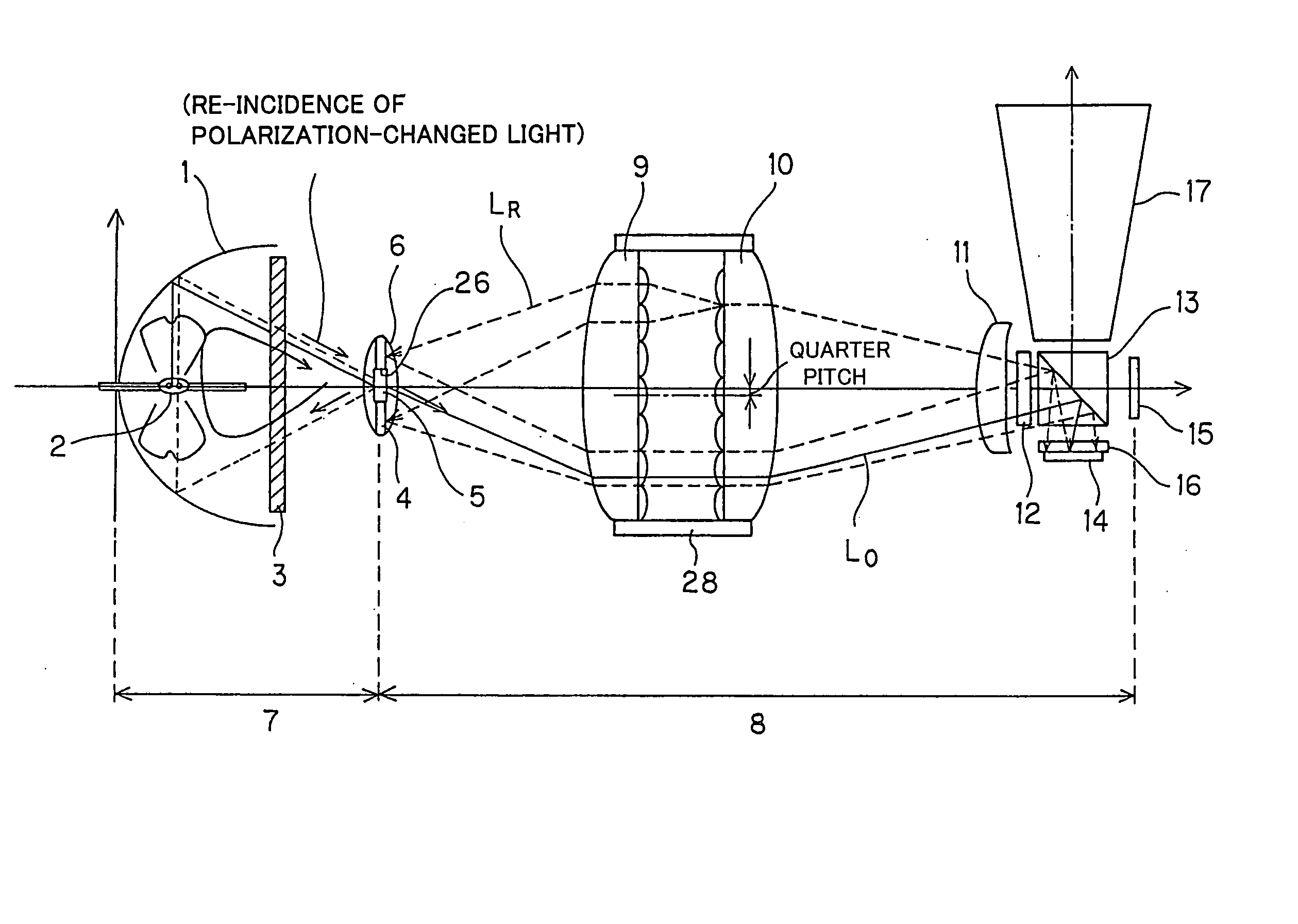
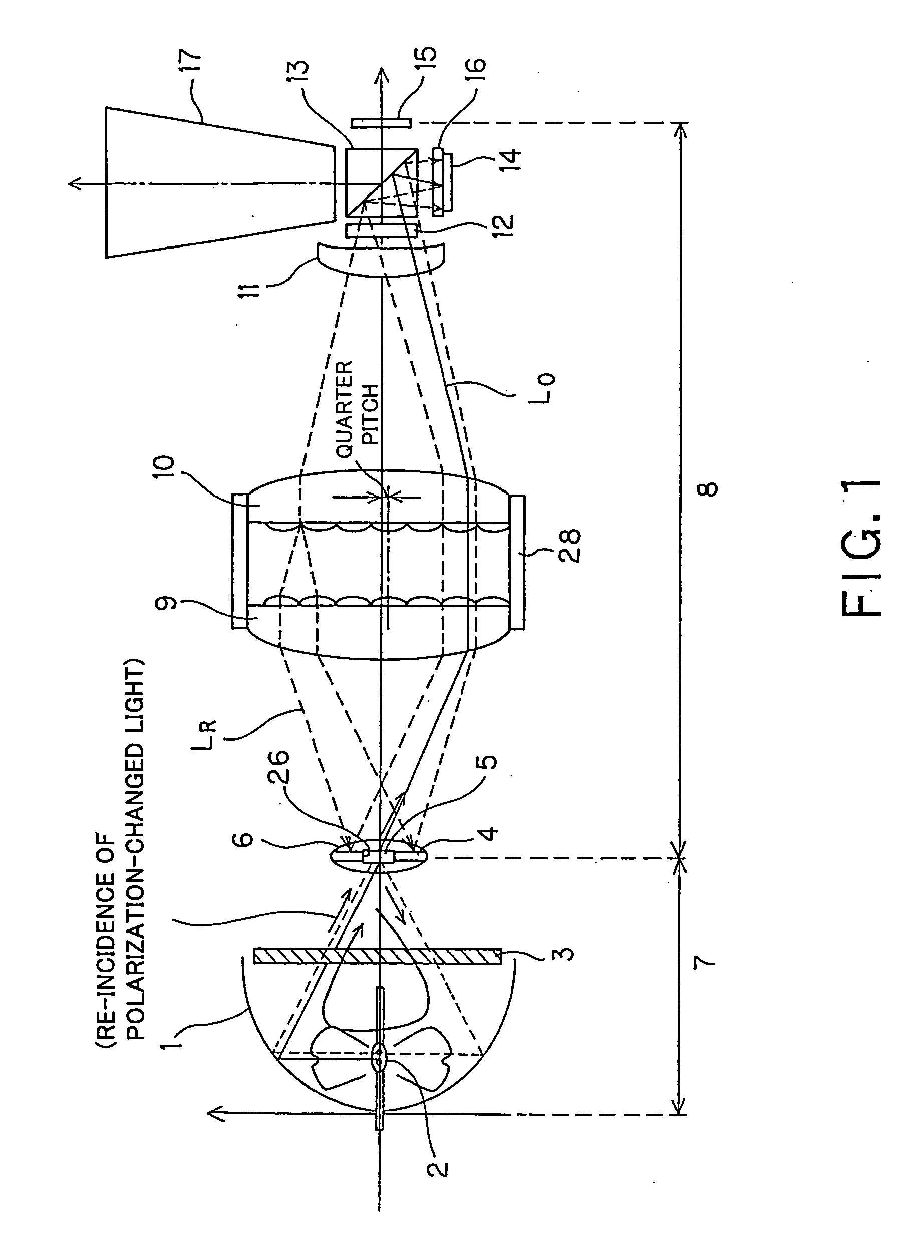
[0091] As shown in FIG. 1, the image display device according to the present invention includes a spheroidal reflecting mirror 1 having a spheroidal shape and open at the end thereof, and a light source 2 disposed on a first focal point of the spheroidal reflecting mirror 1. The light source 2 is a discharge lamp such as a UHP (ultra-high pressure mercury) lamp.

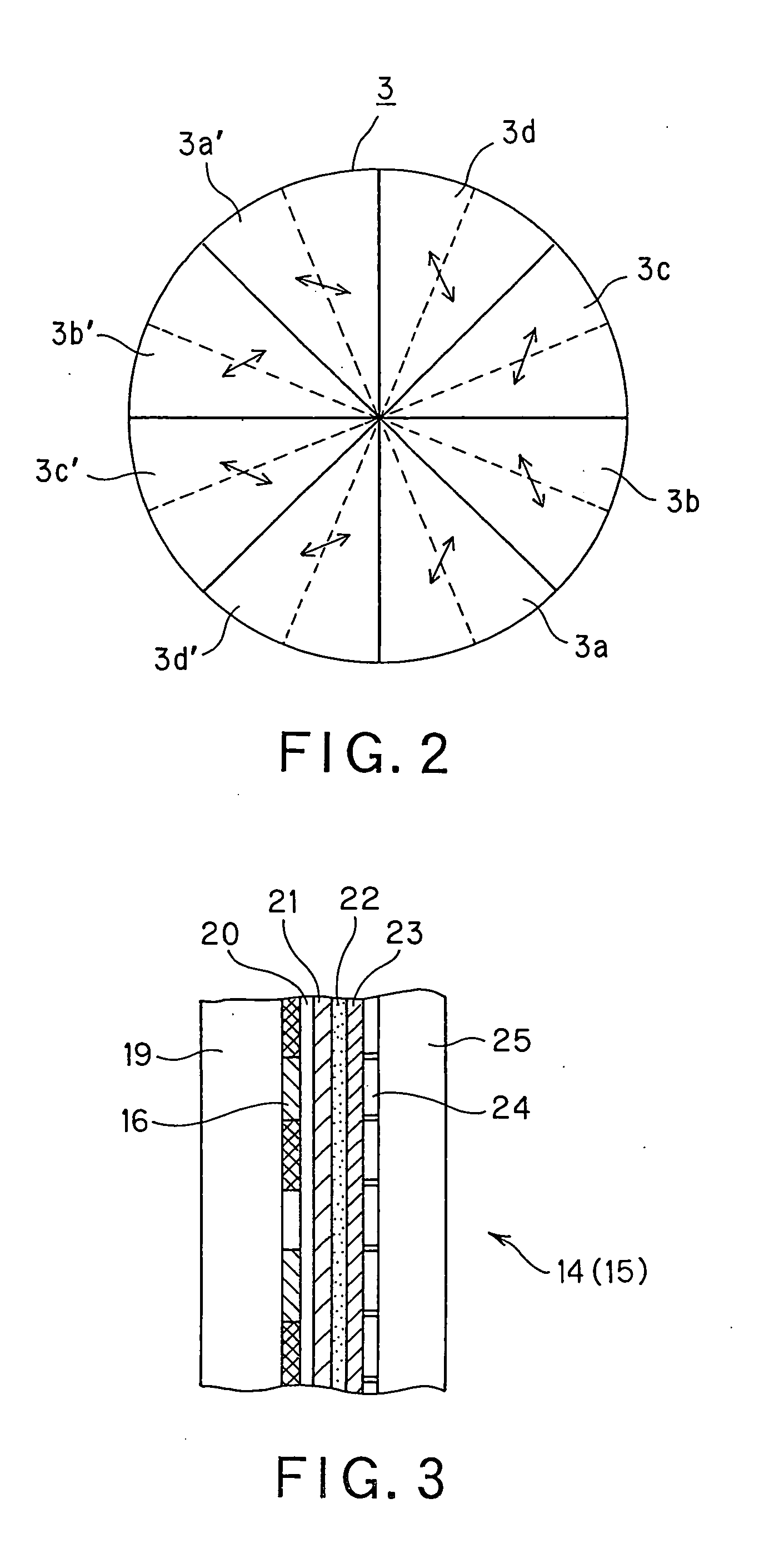
[0092] At the open end of the spheroidal reflecting mirror 1, there is provided a polarization changing element 3. As shown in FIG. 2, the polarization changing element 3 includes a quarter or half wave plate having an even number of areas extending radially and symmetrically with respect to the optical axis.

[0093] Near a second focal point of the spheroidal reflecting mirror 1, there is provided a relay lens block 6 having an opening 26 formed in the center thereof and having dis...


PUM


Abstract

According to the present invention, there is provided an image display device including a non-luminous reflection type spatial light modulating element, illuminating system to illuminate the reflection type spatial light modulating element and a projection lens and in which light from a light source (2) illuminates the reflection type spatial light modulating elements (14, 15) via first and second fly-eye integrators (9, 10). An unnecessary part, not modulated, of the light reflected by the reflection spatial light modulating elements (14, 15) and further by a reflector (4) for recycling. Since the fly-eye integrators (9, 10) are displaced in relation to their optical axes, it is possible to utilize the light with an improved efficiency and prevent any nonuniform illumination from taking place.

Description


Claims


Application Information

Patent Timeline
Owner SONY CORP
Why Eureka
Try Eureka