Method and apparatus for flooding link state packets to achieve faster convergence

a link state packet and speeding technology, applied in the field of flooding link state packets, can solve the problems of prolonging the ability of node b to reach node x, and not being able to compute a spt (shortest path tree), and achieve the effect of efficient flooding

Active Publication Date: 2006-04-06
CISCO TECH INC
View PDF6 Cites 25 Cited by
  • Summary
  • Abstract
  • Description
  • Claims
  • Application Information

AI Technical Summary

Benefits of technology

[0008] In one embodiment, the other LSP's are flooded in an order from lowest to highest cost. In a further aspect, the first node can readily accomplish this efficient flooding because the relative costs of the other LSP's are continuously determined as each LSP is received into the first node. For example, a cost table that lists the relative costs of each received LSP is continuously updated each time a new LSP is received at the first node. This cost table may also list the first node's own LSP at the top of the table. In another example, an LSP data structure that includes a plurality of LSP elements for each of the other LSP's is formed or updated as each of the other LSP's is received. This data structure may also include an element for the first node's own LSP. The LSP data structure also includes a first LSP pointer that points to a first link of one of the LSP elements that corresponds to the lowest cost. The first link is linked to a chain of other links of the other LSP elements in an order corresponding to an ascending order of costs of the other LSP elements.
[0009] In a specific implementation, the flood trigger includes the second node having an interface with the first node and starting or restarting. In a further aspect., the flood trigger includes merging a first network that includes the first node with a second network that includes the second node, and the first and second networks are merged by interfacing the first node and the second node together. In another embodiment, each of the other LSP's includes connectivity information for one or more fourth nodes connected to the corresponding third node and one or more cost values from such corresponding third node to each of the one or more fourth nodes, and determination of the

Problems solved by technology

In this example network, Node X (102) is several hops away from node A. That is, Node Y (104) and Node Z (106) are positioned between Nodes X and A. When the LSP for Node X has the smallest system ID, Node B will receive the LSP for Node X first from Node A. Unfortunately, Node B may not be able to compute an SPT (shortest path tree) using an SPF (shortest path first) algorithm to node X because Node B has not yet received and processed LSP's

Method used


Image

  • Method and apparatus for flooding link state packets to achieve faster convergence
  • Method and apparatus for flooding link state packets to achieve faster convergence
  • Method and apparatus for flooding link state packets to achieve faster convergence

Examples


Embodiment Construction

[0021] Reference will now be made in detail to a specific embodiment of the invention. An example of this embodiment is illustrated in the accompanying drawings. While the invention will be described in conjunction with this specific embodiment, it will be understood that it is not intended to limit the invention to one embodiment. On the contrary, it is intended to cover alternatives, modifications, and equivalents as may be included within the spirit and scope of the invention as defined by the appended claims. In the following description, numerous specific details are set forth in order to provide a thorough understanding of the present invention. The present invention may be practiced without some or all of these specific details. In other instances, well known process operations have not been described in detail in order not to unnecessarily obscure the present invention.

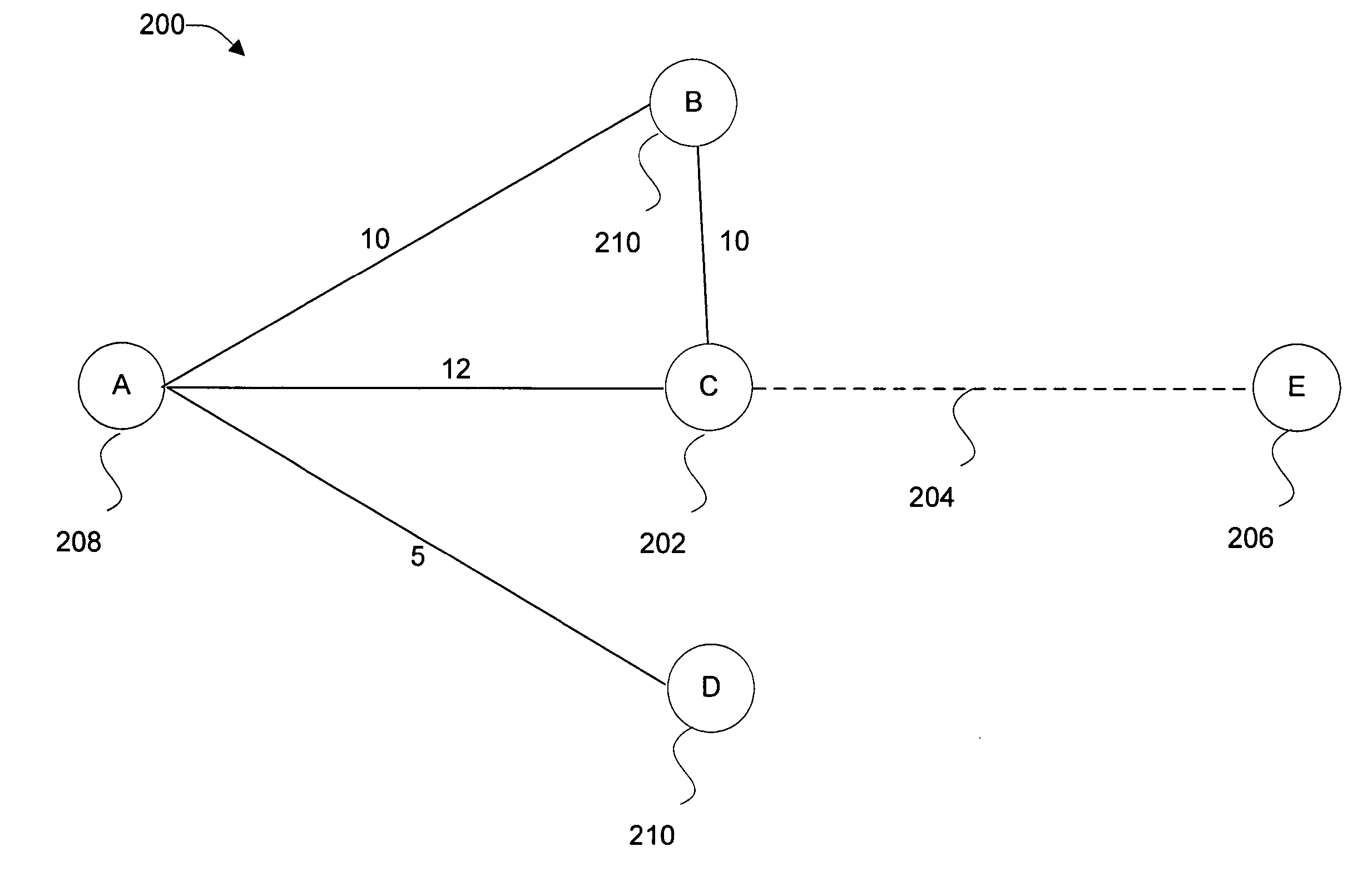
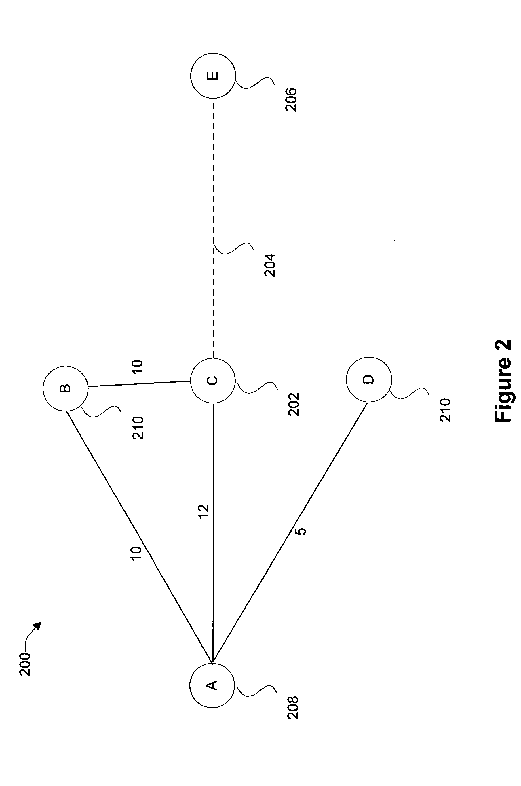
[0022] Techniques of the present invention are described herein with respect to FIG. 2, which is a diagram...


PUM


Abstract

Disclosed are methods and apparatus for flooding link state packets or packet data units (LSP's) from a first node to one other LSP receiving node, where the LSP's are flooded in an order that is related to relative costs of various paths emanating from the first node. That is, the first node sends its own LSP first since the first node has no cost relative to itself. The first node then sends other LSP's that are associated with a plurality of other LSP sending nodes that have previously flooded their LSP's to the first node, and these other LSP's are sent by the first node to the other LSP receiving node in an order related to the relative costs associated with the paths from the first node to each of the other LSP sending nodes which had previously sent the other LSP's to the first node.

Description

BACKGROUND OF THE INVENTION [0001] The present invention relates to apparatus and methods for facilitating routing protocol in a computer network. More specifically, it relates to flooding Link State Packets or Packet Data Units (LSP's), which are used in a link state type protocol, such as the IS-IS protocol. [0002] In a network that uses the IS-IS protocol, for example, each node generates a set of LSP's that describe its connectivity to its neighbors and floods these LSP's to its neighbors at appropriate times as specified by the protocol or customized programming. This connectivity information specifies who is connected to whom and the cost associated with each connection, such as a value that is configured by an operator to correspond to a speed of a particular connection. Thus, each node receives connectivity information in the form of LSP's from its neighbors. The LSP's received at a particular node are then flooded by the particular node to its neighbors and, hence, propagat...

Claims


Application Information

Patent Timeline
IPC IPC(8): H04L12/26
CPCH04L45/02H04L45/32H04L45/03
Inventor LUONG, STEVEN V.OU, HEIDI H.REDWINE, GERALDNG, JAMES L.ECKHARDT, KEVIN M.STURGESS, SCOTT R.MOORE, STEVEN
Owner CISCO TECH INC
Why Eureka
Try Eureka