Intermediate density marker and a method using such a marker for radiographic examination

a radiographic examination and intermediate density technology, applied in the field of radiography, can solve the problems of metallic markers, ct scanners, and tissue detail that falls within the shadow of markers, and achieve the effect of avoiding the shadow of markers

Inactive Publication Date: 2006-04-06
BEEKLEY A CT
View PDF8 Cites 13 Cited by
  • Summary
  • Abstract
  • Description
  • Claims
  • Application Information

AI Technical Summary

Benefits of technology

[0017] Each of the markers comprising the system has a radiographic density and thickness which permit the marker, upon exposure of the marker and an underlying tissue structure to x-ray radiation of a specific energy, to both cast a radiographic shadow and transmit sufficient radiation to image anatomical detail present in the underlying tissue structure.

Problems solved by technology

The disadvantage here is that any tissue detail that falls within the shadow of the marker will be completely obscured.
Metallic markers also create problems when employed in computerized tomography (CT) applications.
CT scanners, which typically operate in the range of 60 to 80 KV, cannot tolerate the presence of metallic objects in the radiographic field.
Such dense objects cause streaking which degrades the radiographic image.
This problem is made more acute by the fact that the marker must have sufficient surface area to be imaged in at least one section radio graphed by the scanner.
A metallic marker having the required surface area would completely disrupt the scanning apparatus.
Unfortunately, one result of such a practice is that the patient's body is exposed to potentially harmful radiation beyond the specific site being examined.
Again, the unfortunate result is that the patient is exposed to greater dosage of potentially harmful radiation.
Further, because such a marker is necessarily of small size with a correspondingly small shadow, there is an inherent difficulty in discerning variations in the size and shape of the marker's image on the film.
Thus, the information that can be conveyed by markers of this type is limited.
Finally, markers comprising lead, mercury and other toxic heavy metals cannot be deposited in landfills or incinerated and thus present a potential environmental hazard if improperly disposed of.
This problem is exacerbated by the fact that during radiographic examination procedures markers are often contaminated by body fluids.

Method used


Image

  • Intermediate density marker and a method using such a marker for radiographic examination
  • Intermediate density marker and a method using such a marker for radiographic examination
  • Intermediate density marker and a method using such a marker for radiographic examination

Examples


Embodiment Construction

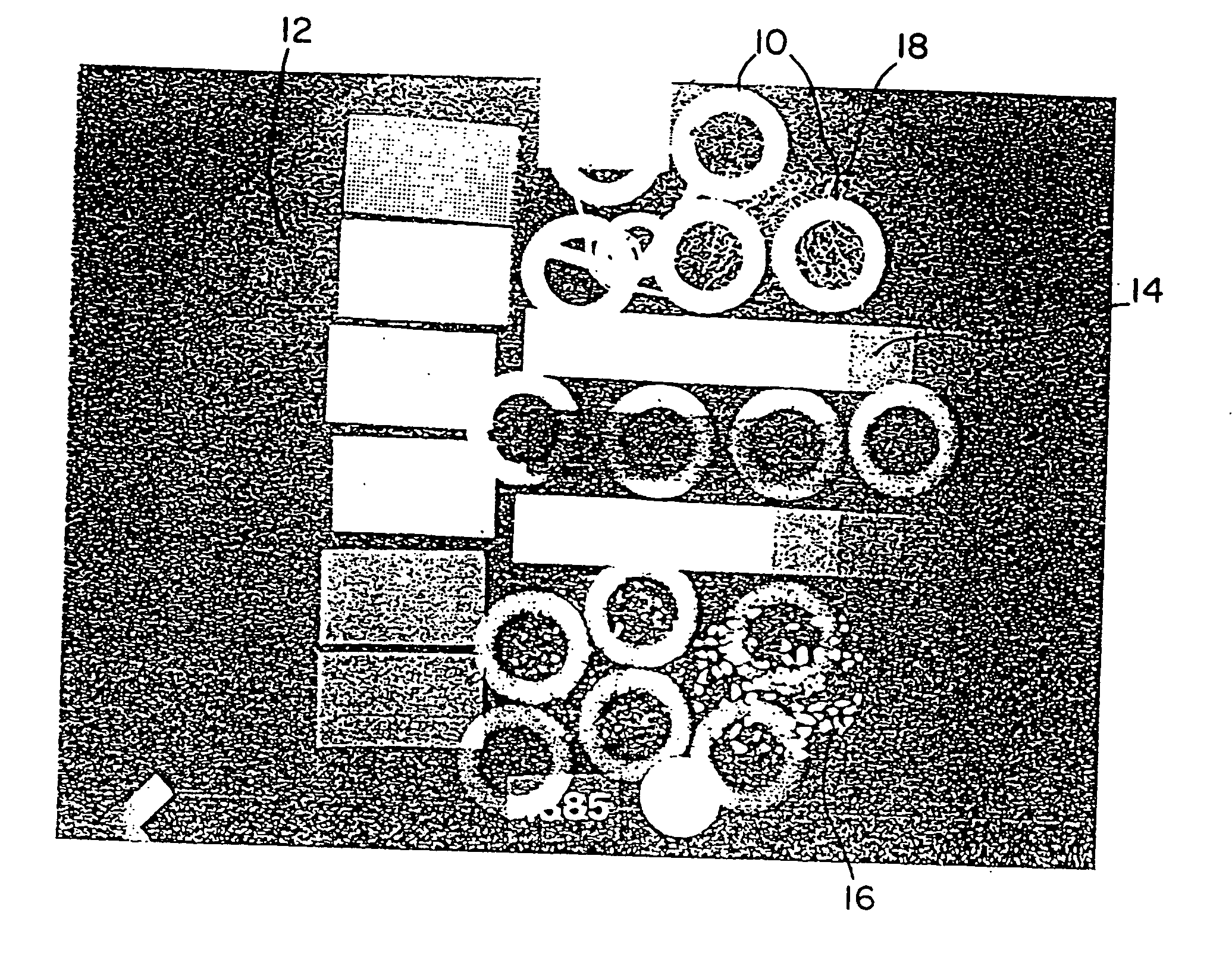
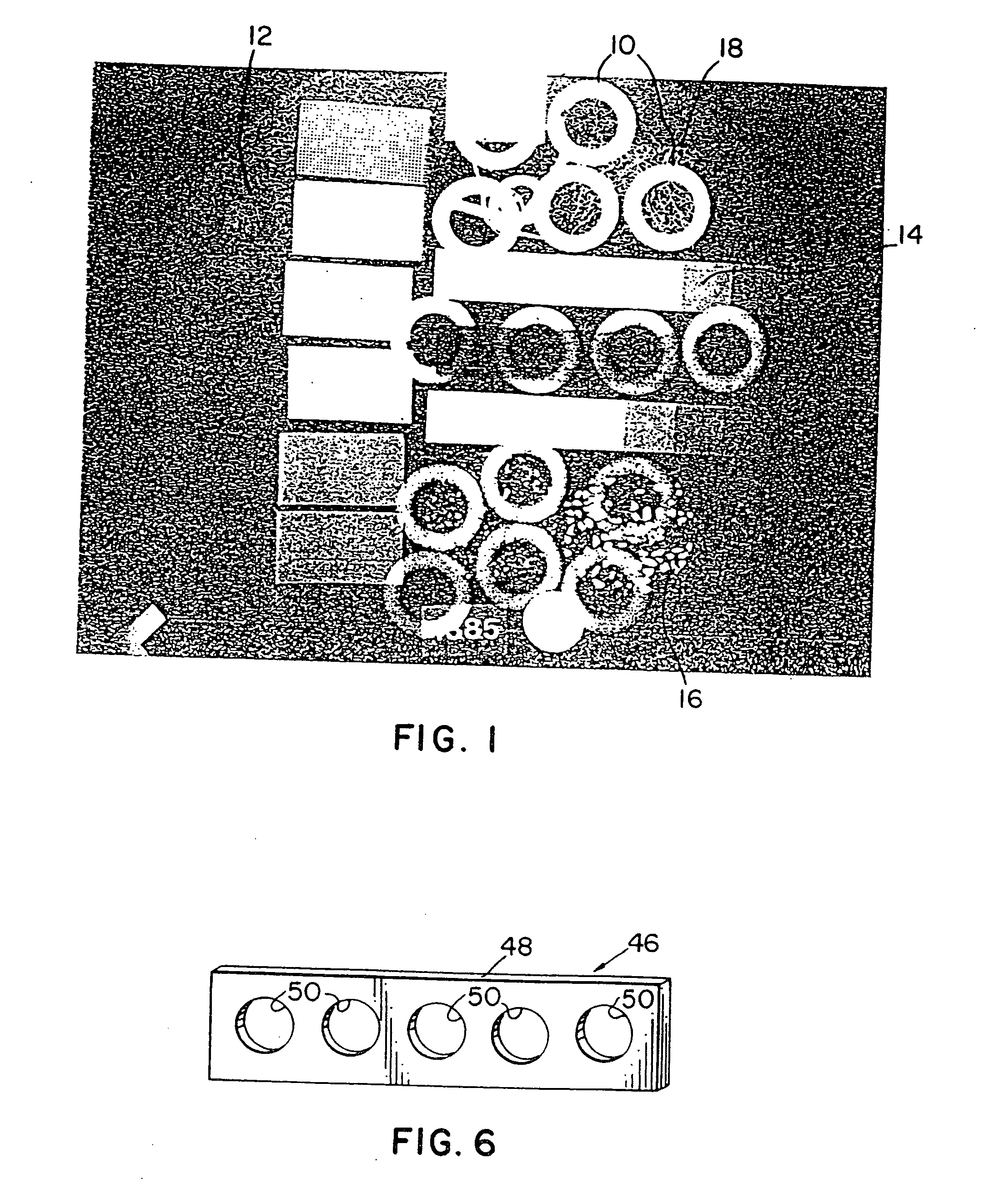
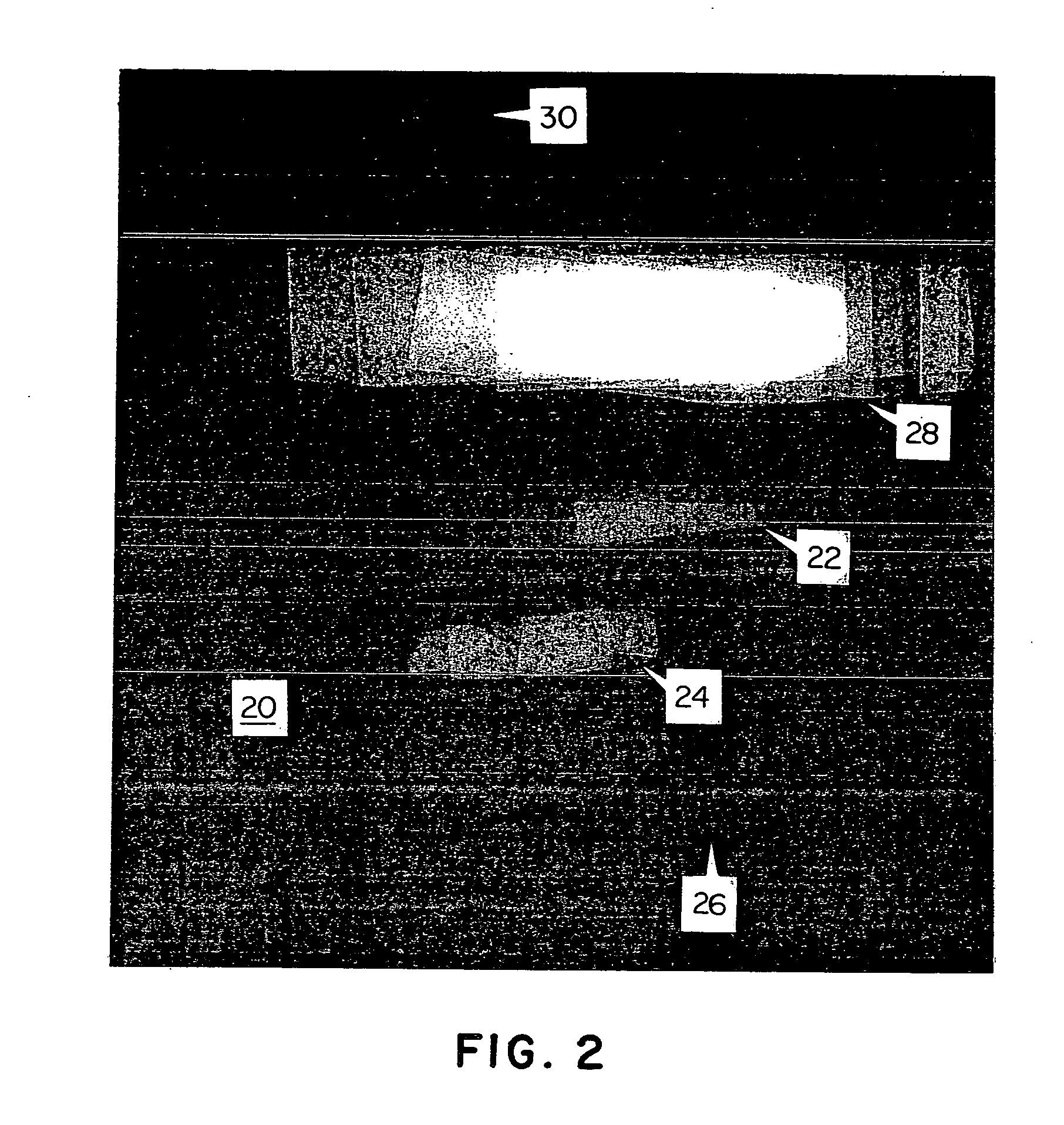
[0026] The most important factor regarding the detail recorded in a radiographic image is the disparity in light and dark or shadow intensity between adjacent objects. This is called image contrast and refers to the difference in the optical density between areas or objects imaged on a detectors, commonly photographic film. As x-rays pass through a patient, or other objects, they are absorbed, to varying degree, by the materials through which they pass. The principal determinant of contrast is the radiation attenuation property of each material, which is a function of the material's elemental and chemical composition. Materials of higher atomic number and density (weight per volume) have a greater ability to absorb x-rays and reduce or attenuate the beam.

[0027] In the diagnostic x-ray spectrum, for example, bone, rich in calcium, contrasts very well with the surrounding muscle and other soft tissues which have a density equivalent to water. Fatty tissue, which is only 10% less dens...


PUM


Abstract

The present invention provides a partially radiolucent, partially radiopaque marker and a method for using such a marker for radiographic examination. The marker and the disclosed method may be employed for the examination of tissue structures of various densities. The radiographic density and thickness of the marker are selected so that when the marker and an underlying tissue structure are exposed to x-ray radiation of a specified energy, the marker casts a legible shadow without obscuring anatomical detail present in the underlying tissue structure. The invention also provides a system of partially radiolucent, partially radiopaque markers for use in the method of radiographic examination taught by the invention.

Description

CROSS-REFERENCE TO RELATED APPLICATIONS [0001] This application is a continuation of application Ser. No. 09 / 372,835 filed Aug. 12, 1999, which is a continuation of application Ser. No. 08 / 934,121 filed Sep. 19, 1997, now U.S. Pat. No. 6,041,094, which is a continuation of application Ser. No. 08 / 372,654, filed Jan. 13, 1995, now abandoned, which is a continuation-in-part of application Ser. No. 08 / 059,201, filed May 7, 1993, now U.S. Pat. No. 5,383,233, which is a continuation-in-part of the co-pending application Ser. No. 09 / 372,835, filed Aug. 12, 1999, all of which are expressly herein incorporated by reference as part of the present disclosure.BACKGROUND OF THE INVENTION [0002] This present invention relates generally to the field of a radiography and, more particularly, to a marker of intermediate density and a method of radiographic examination using such a marker. The invention further relates to a system of radiographic markers for use in such a method. [0003] To convey per...

Claims


Application Information

Patent Timeline
Patent Type & Authority Applications(United States)
IPC IPC(8): H05G1/28A61B5/00A61B6/00
CPCA61B5/01A61B6/583
Inventor RUSSELL, DONALD G.
Owner BEEKLEY A CT
Why Eureka
Try Eureka