Pop-up flash unit for camera

Inactive Publication Date: 2006-04-06
ASIA OPTICAL INT LTD
View PDF8 Cites 20 Cited by
  • Summary
  • Abstract
  • Description
  • Claims
  • Application Information

AI Technical Summary

Benefits of technology

[0010] One object of the present invention is to provide a

Problems solved by technology

However, with more recent cameras that has a large sized taking lens to achieve high zoom ratio, a built-in flash unit is generally insufficient to meet the performance requirements.
Furthermore, since electronic viewfinders (EVF) are increasingly incorporated in cameras instead of standard optical viewfinders (OVF), the camera design correspondingly becomes increasingly compact, which results in limited interior space available in the camera.
In addition, with the current trend of cameras toward compactness, the relative closeness of the flash unit and the taking lens can cause an undesirable phenomenon known as “red-eye” to occur.
Such a pop-up flash unit occupies a large space and sign

Method used


Image

  • Pop-up flash unit for camera
  • Pop-up flash unit for camera
  • Pop-up flash unit for camera

Examples


Embodiment Construction

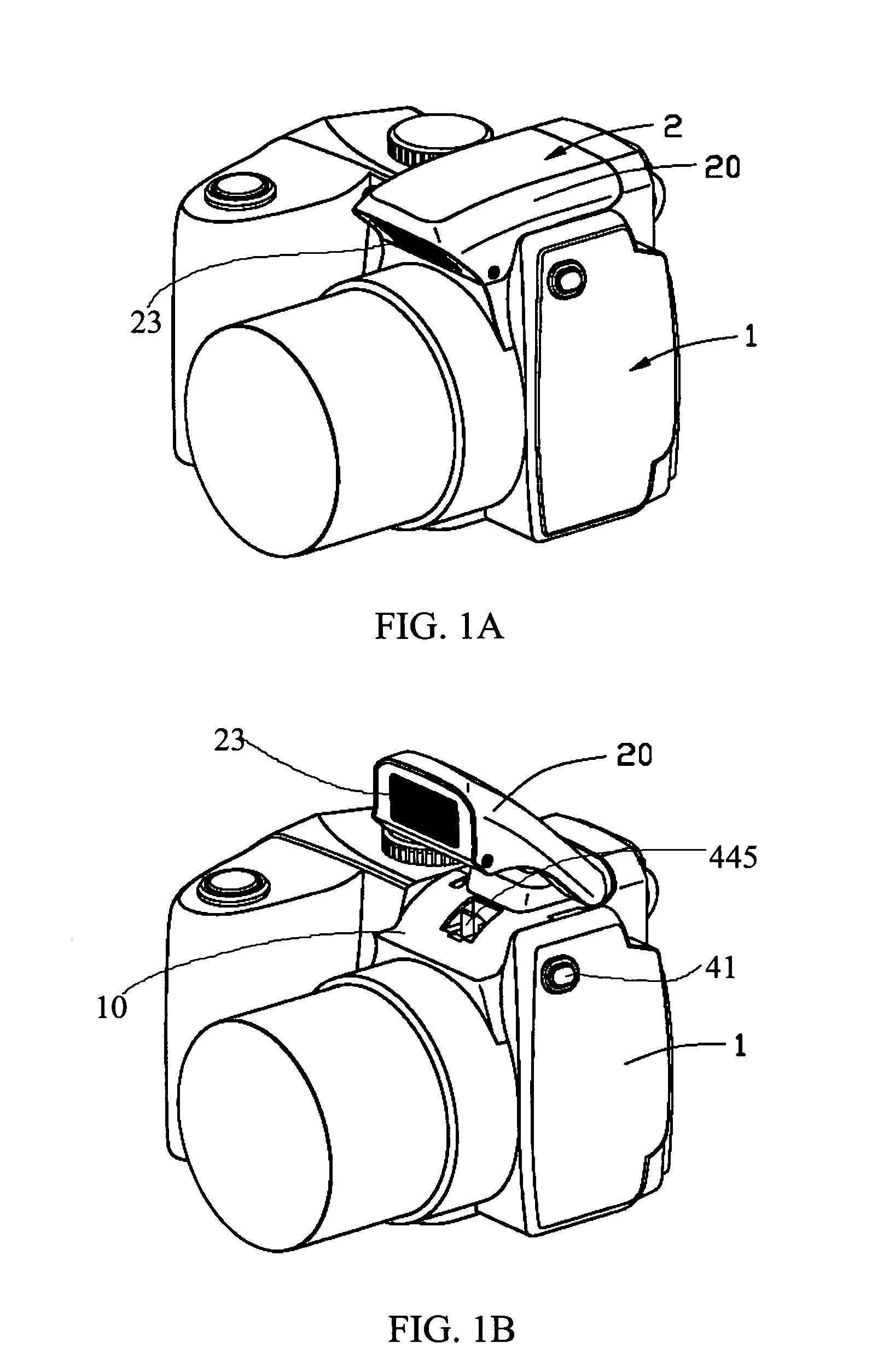
[0025] Referring to FIGS. 1A and 1B, a pop-up flash unit 2 in accordance with the present invention is adapted to be rotatably mounted on a photographic device body such as a digital camera body 1. The pop-up flash unit 2 is movable between a retracted position (the position shown in FIG. 1A) for storage, where a flash lens 23 thereof faces downwards, and a projected position (the position shown in FIG. 1B) for operating, where the flash lens 23 is raised into place facing a photographic object ahead of the camera.

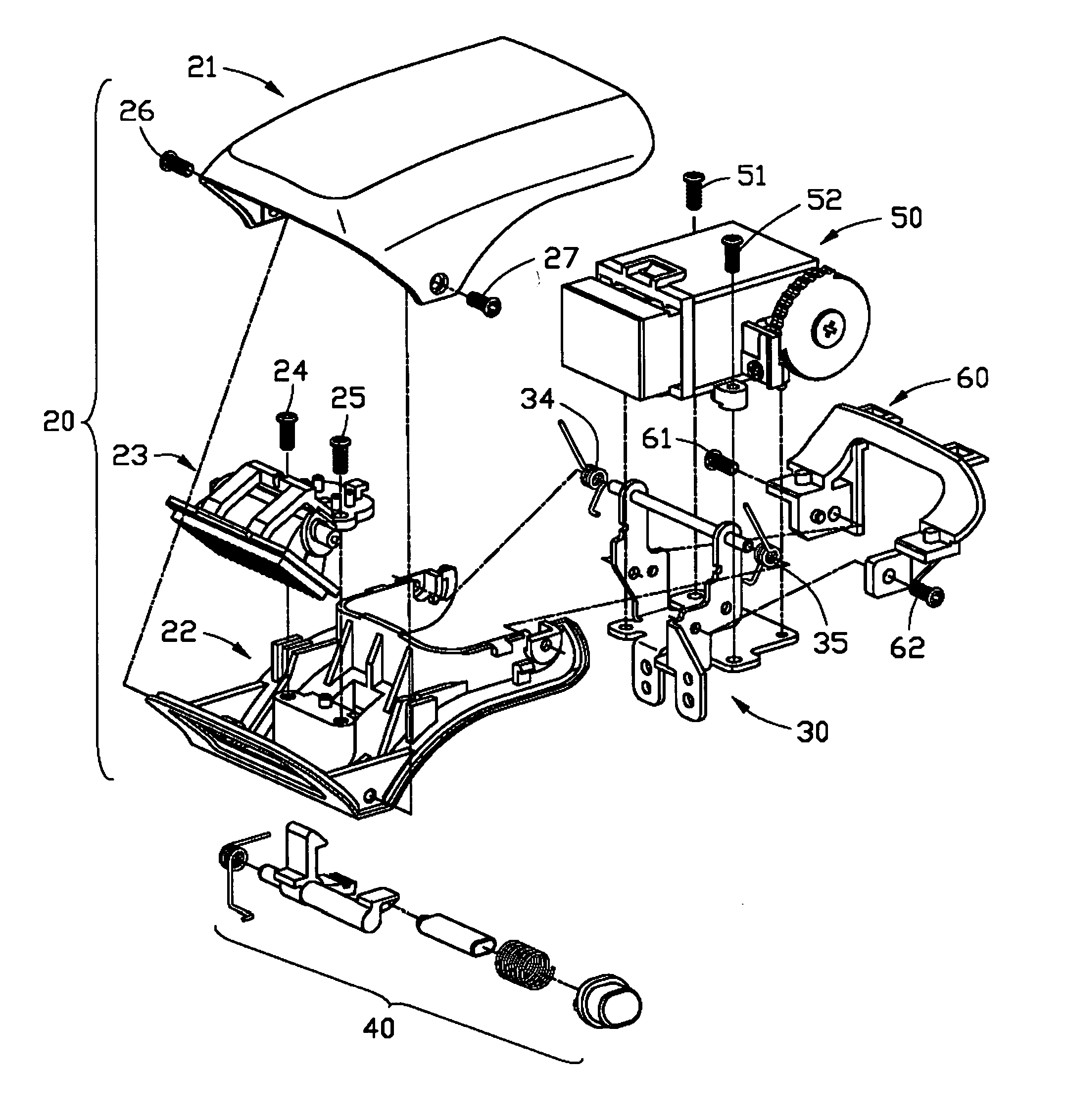
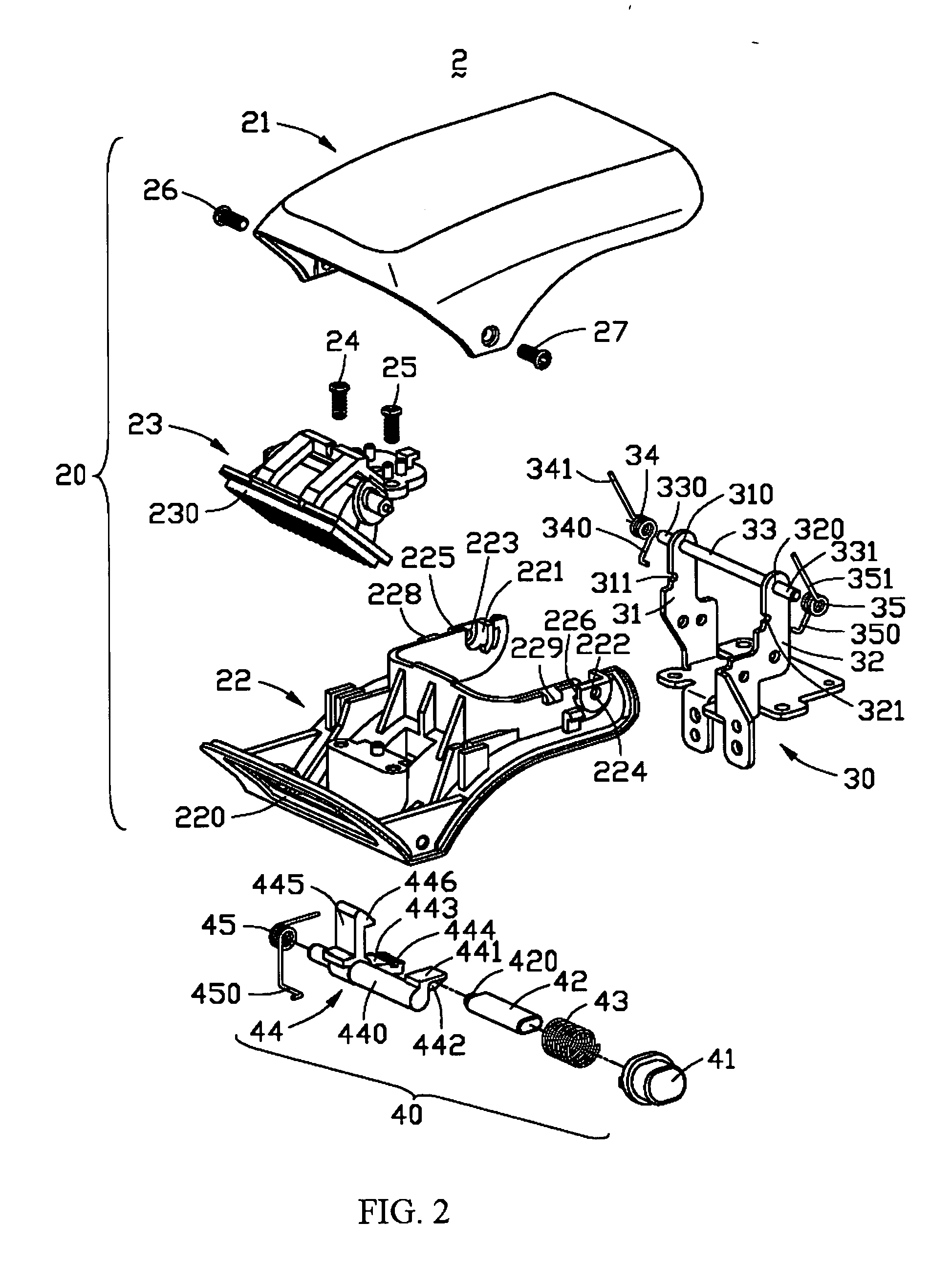
[0026] An exploded, perspective view of the pop-up flash unit 2 in accordance with the present invention is shown in FIG. 2. The pop-up flash unit 2 includes a flash member 20, a mounting seat 30 disposed within the camera body 1 for movably supporting the flash member 20 thereon, a driving device 40 for driving the flash member 20 from the retracted position to the projected position, a pair of first torsion members 34, 35 for providing a resilient restoring force to the...


PUM


Abstract

A pop-up flash unit (2) for a camera includes a mounting seat (30) disposed in the camera body, a flash member (20) rotatably mounted on the mounting seat between a projected position for operating and a retracted position for storage, a driving device (40) substantially disposed in the camera body for permitting movement of the flash member from the retracted position to the projected position, a pair of first torsion members (34, 35) for providing a resilient restoring force to the flash member to thereby permit movement of the flash member from the retracted position to the projected position, and a second torsion member (45) for reliably retaining the flash member in the retracted position. The flash member is retained in its retracted position via a latching engagement with the driving device.

Description

BACKGROUND OF THE INVENTION [0001] 1. Field of the Invention [0002] The present invention relates to a flash unit for a camera, and particularly relates to a pop-up flash unit for a camera that is movable between a projected position and a retracted position. [0003] 2. Description of Prior Art [0004] Flash units for providing artificial illumination during photographic exposures under conditions of low ambient scene light intensity are well known in the art. However, with more recent cameras that has a large sized taking lens to achieve high zoom ratio, a built-in flash unit is generally insufficient to meet the performance requirements. Furthermore, since electronic viewfinders (EVF) are increasingly incorporated in cameras instead of standard optical viewfinders (OVF), the camera design correspondingly becomes increasingly compact, which results in limited interior space available in the camera. In addition, with the current trend of cameras toward compactness, the relative closen...

Claims


Application Information

Patent Timeline
IPC IPC(8): G03B15/03
CPCG03B15/0442G03B15/05G03B2215/0507
Inventor LIU, YING-FA
Owner ASIA OPTICAL INT LTD
Why Eureka
Try Eureka