Heat-fixing device

a heating device and heat-fixing technology, applied in the direction of electrographic process apparatus, instruments, optics, etc., can solve the problems of increasing the amount of computing, affecting the efficiency of heating, and affecting the quality of heating

Inactive Publication Date: 2006-04-06
PANASONIC CORP
View PDF8 Cites 23 Cited by
  • Summary
  • Abstract
  • Description
  • Claims
  • Application Information

AI Technical Summary

Benefits of technology

[0012] It is an object of the present invention to provide a heat-fixing apparatus that enables a rise in temperature of a heating member to be closely tracked, and an excessive rise in temperature of the heating member to be obviated, by means of a simple configuration and irrespective of differences in the operating mode, such as immediately after a rise in temperature or during continuous operation.

Problems solved by technology

In a heat-fixing apparatus, the heating member may be damaged if the temperature of the heating member is raised too high, and it is therefore necessary to prevent an excessive rise in temperature of the heating member.
That is to say, when a sensor is installed at a distance from the heating member, if the heat-producing member stops rotating due to the occurrence of an abnormal state the temperature cannot be detected, and the heating member will rise excessively in temperature.
However, problems with the above-described heat-fixing apparatus of Patent Document 1 are that, since the resistivity of magnetic metallic film is calculated and temperature is detected from the calculated resistivity, the amount of computing increases and the circuit configuration becomes more complex.
Also, if there is nonuniformity in the magnetic metallic film, a difference arises between the detected temperature and the actual temperature, and therefore this heat-fixing apparatus is inadequate in terms of preventing an excessive rise in temperature of the magnetic film.
Furthermore, even though the exciting coil is located in the vicinity of the magnetic metallic film, a certain amount of time is required for the heat of the magnetic metallic film to be conveyed to the exciting coil, and the temperature of the magnetic metallic film and the temperature of the exciting coil are not necessarily the same.
As a result, it is not easy to measure the temperature of the magnetic metallic film accurately.

Method used


Image

  • Heat-fixing device
  • Heat-fixing device
  • Heat-fixing device

Examples


embodiment 1

(1) Overall Configuration

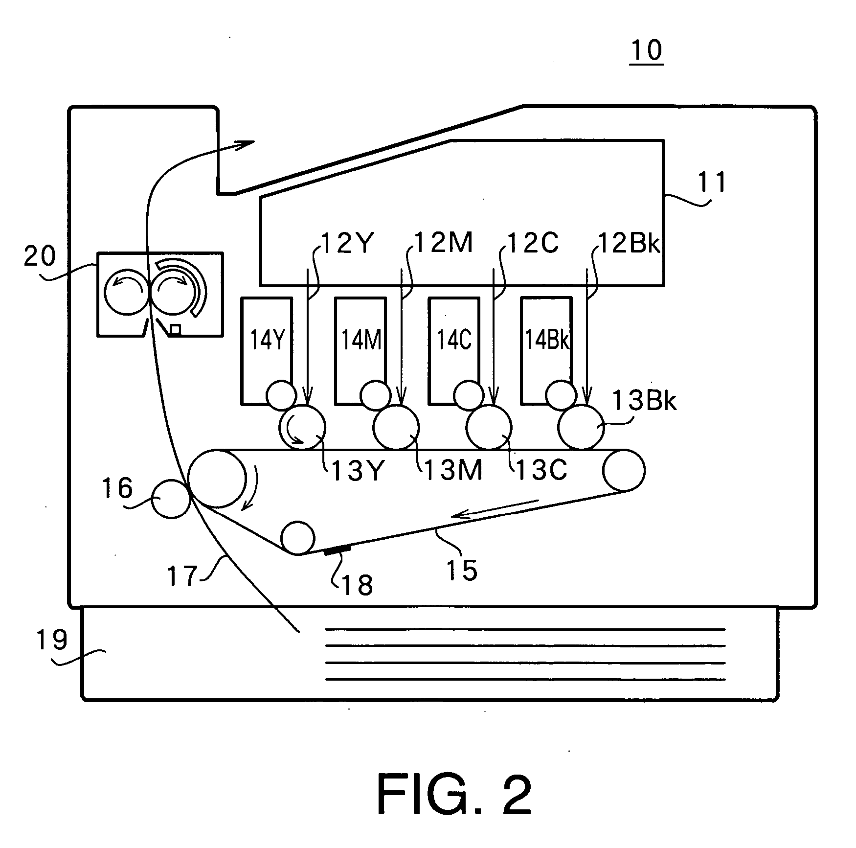
[0037]FIG. 2 shows the overall configuration of an image forming apparatus. In image forming apparatus 10, four laser beams 12Y, 12M, 12C, and 12Bk corresponding to image signals are output from an exposure section 11. As a result, latent images are formed by laser beams 12Y, 12M, 12C, and 12Bk on photosensitive bodies 13Y, 13M, 13C, and 13Bk. Developing units 14Y, 14M, 14C, and 14Bk develop the latent images on photosensitive bodies 13Y, 13M, 13C, and 13Bk by applying toner. There are four combinations—Y, M, C, and Bk—of these photosensitive bodies and developing units, with toner of four colors—yellow, magenta, cyan, and black—contained in developing units 14Y, 14M, 14C, and 14Bk respectively. Y, M, C, and Bk are appended to the numbers indicating the above-described members for each color.

[0038] Four-color toner images 18 formed on photosensitive bodies 13Y, 13M, 13C, and 13Bk are superimposed on the surface of an intermediate transfer belt 15 that is ...

embodiment 2

[0095]FIG. 10, in which parts corresponding to those in FIG. 6 are assigned the same codes as in FIG. 6, shows the configuration of an exciting circuit 50 according to Embodiment 2 of the present invention. Exciting circuit 50 is used instead of exciting circuit 30 in heat-fixing apparatus 20 described in Embodiment 1.

[0096] In the case of exciting circuit 30 of Embodiment 1, variation of the frequency of a high-frequency current necessary to supply constant power to exciting coil 24 is detected, and the current supply to exciting coil 24 is halted. By contrast, in the case of exciting circuit 50 of this embodiment, variation of an applied voltage necessary to supply constant power to exciting coil 24 is detected, and the current supply to exciting coil 24 is halted. That is to say, in this embodiment, an applied voltage is used instead of a switching frequency as an operation state amount constituting the basis of control. However, the circuit configuration for detecting variation...

embodiment 3

[0107]FIG. 13, in which parts corresponding to those in FIG. 6 are assigned the same codes as in FIG. 6, shows the configuration of an exciting circuit 30 according to Embodiment 3 of the present invention. This exciting circuit 30 is used instead of the exciting circuit 30 in heat-fixing apparatus 20 described in Embodiment 1. Heat-fixing apparatus 20 according to this embodiment supplies a high-frequency current obtained by means of inverter 34 to exciting coil 24 via thermostats 60.

[0108] In this embodiment, two thermostats 60 are installed connected in a cascade arrangement in the axial-direction center of center core 25a of rear core 25 as shown in FIG. 3 and FIG. 5. However, the number and installation location of thermostats 60 are not limited to this case, and any location may be used that enables an excessive rise in temperature of heat-producing belt 21d to be detected. In this embodiment, thermostats 60 cut the current at both ends when the temperature of an internal tem...


PUM


Abstract

A heat-fixing apparatus is provided that enables a rise in temperature of a heating member to be closely tracked, and an excessive rise in temperature of the heating member to be obviated, a simple configuration and irrespective of differences in the operating mode, such as immediately after a rise in temperature or during continuous operation. Different threshold values are set in accordance with different modes, such as a warm-up mode and a fixing operation mode. Threshold decisions on a switching frequency controlled by a frequency control section are made using different threshold values, according to the mode. A switching frequency of switching elements are varied so that power necessary in each mode is supplied to an exciting coil. An excessive rise in temperature is prevented in each mode by halting a switching element drive in accordance with the threshold decision.

Description

TECHNICAL FIELD [0001] The present invention relates to a heat-fixing apparatus, and is suitable for application to a heat-fixing apparatus that fixes unfixed toner by means of heating used in a copier, printer, facsimile, or the like, for example. BACKGROUND ART [0002] A heat-fixing apparatus of this kind uses heat and pressure to fix toner attached to recording paper by means of an exposure apparatus and transfer roller, for example. Heretofore, a heat-fixing apparatus that uses induction heating has been proposed as one such heat-fixing apparatus. [0003] This heat-fixing apparatus using induction heating performs induction heating, by means of an induction field, of a heating member such as a heat-producing belt located in the vicinity of an exciting coil, by passing a high-frequency current through the exciting coil. Then, toner on the recording paper is heated and fixed using the induction-heated heating member. In comparison with a heat-fixing apparatus that uses a halogen lam...

Claims


Application Information

Patent Timeline
Patent Type & Authority Applications(United States)
IPC IPC(8): G03G15/20
CPCG03G15/205G03G2215/2029
Inventor ASAKURA, KENJIFUJIMOTO, KEISUKEIMAI, MASARUKATAKABE, NOBORU
Owner PANASONIC CORP
Why Eureka
Try Eureka