DC-DC converter

A DC-DC converter technology, applied in the field of DC-DC converters, can solve problems such as poor anti-noise ability, large package area, and increased cost, and achieve the goals of improving anti-noise ability, simplifying circuit structure, and reducing chip cost Effect

Active Publication Date: 2013-07-31
HUAWEI TECH CO LTD
View PDF7 Cites 10 Cited by
  • Summary
  • Abstract
  • Description
  • Claims
  • Application Information

AI Technical Summary

Problems solved by technology

[0004] The purpose of the present invention is to provide a DC-DC converter, which aims to solve the problem that although the existing DC-DC converter can realize fixed switching frequency contro

Method used


Image

  • DC-DC converter
  • DC-DC converter
  • DC-DC converter

Examples


Embodiment 1

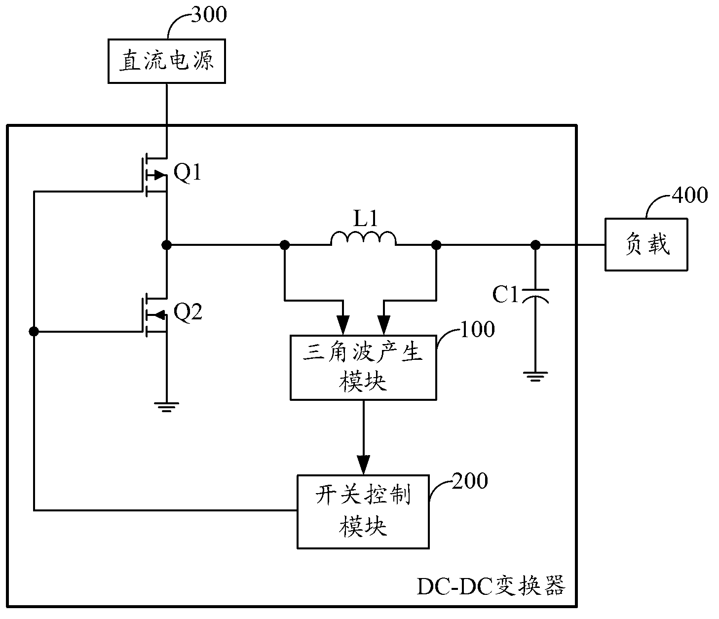
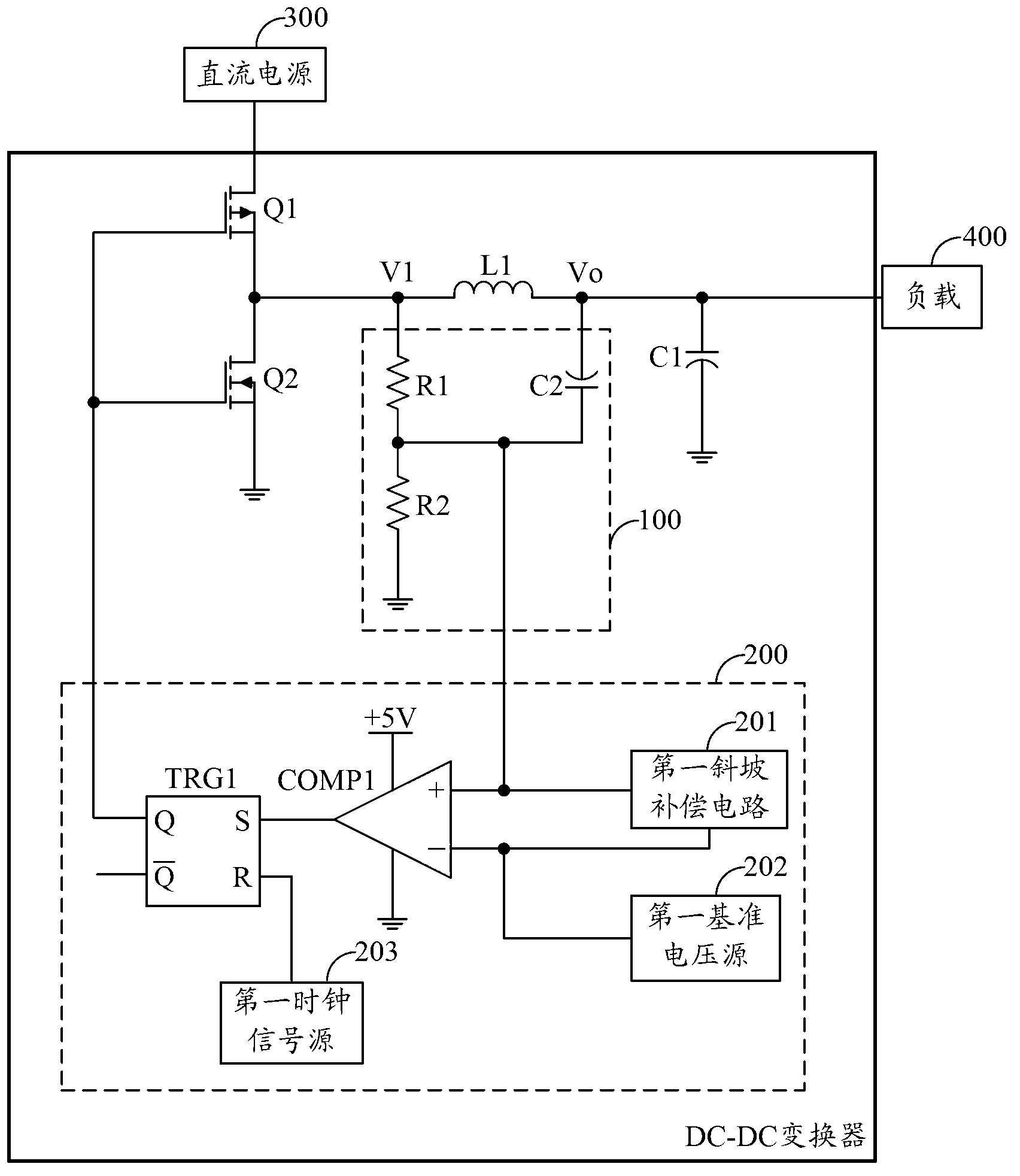
[0024] figure 2 An example circuit structure of the DC-DC converter provided by the first embodiment of the present invention is shown. For the convenience of description, only the parts related to the first embodiment of the present invention are shown, and the details are as follows:

[0025] As an embodiment of the present invention, the triangular wave generating module 100 includes a resistor R1, a resistor R2 and an energy storage capacitor C2, the first end of the resistor R1 is connected to the first input end of the triangular wave generating module 100, and the second end of the resistor R1 is connected to the resistor R2. The first end of the resistor R2 is connected to the positive pole of the energy storage capacitor C2, the second end of the resistor R2 is grounded, and the positive pole and the negative pole of the energy storage capacitor C2 are respectively connected to the output end and the second input end of the triangular wave generating module 100.

[0...

Embodiment 2

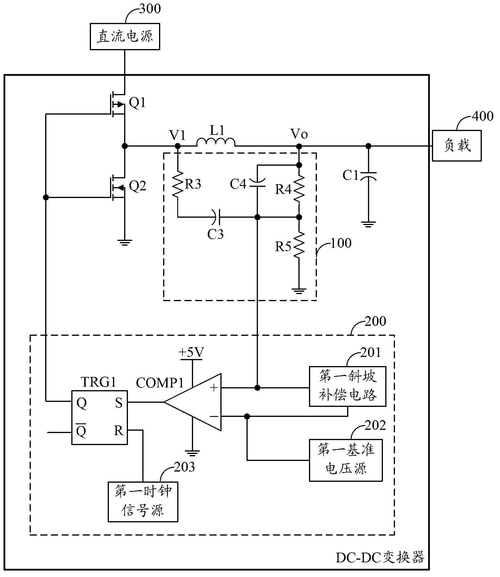
[0035] image 3 An example circuit structure of the DC-DC converter provided by the second embodiment of the present invention is shown. For the convenience of description, only the parts related to the second embodiment of the present invention are shown, and the details are as follows:

[0036] As an embodiment of the present invention, the triangular wave generating module 100 includes:

[0037] Resistor R3, energy storage capacitor C3, energy storage capacitor C4, resistor R4 and resistor R5;

[0038] The first end of the resistor R3 is connected to the first input end of the triangular wave generating module 100, the second end of the resistor R3 is connected to the negative pole of the energy storage capacitor C3, and the positive pole of the energy storage capacitor C3 is connected to the output end of the triangular wave generating module 100. The negative electrode of the energy storage capacitor C4 is connected to the first end of the resistor R4, the first end of t...

Embodiment 3

[0045] Figure 4 The example circuit structure of the DC-DC converter provided by the third embodiment of the present invention is shown. For the convenience of description, only the parts related to the third embodiment of the present invention are shown, and the details are as follows:

[0046] The internal structure of the triangular wave generating module 100 in the DC-DC converter provided in this embodiment is the same as the internal structure of the triangular wave generating module 100 provided in the first embodiment of the present invention, so details are not repeated here.

[0047] As an embodiment of the present invention, the switch control module 200 includes:

[0048] The second comparator COMP2, the second RS flip-flop TRG2, the second slope compensation circuit 210, the second reference voltage source 220 and the second clock signal source 230;

[0049] The inverting input terminal of the second comparator COMP2 is connected to the input terminal of the swi...


PUM


Abstract

The invention is applied to the field of direct current (DC) conversion, and provides a DC-DC converter. The DC-DC converter comprising a triangular wave generation module and a switch control module is adopted, the triangular wave generation module generates a triangular wave signal according to voltage across an energy storage inductor L1, and the switch control module outputs a control level according to a clock signal generated in the switch control module and the triangular wave signal to control a PMOS (P-channel Metal Oxide Semiconductor) power tube and an NMOS (N-channel Metal Oxide Semiconductor) power tube to perform switching operation according to the preset switching frequency, so that fixed switching frequency control on the PMOS power tube and the NMOS power tube is achieved; a circuit structure of the DC-DC converter is simplified on the premise that voltage conversion is performed on DC; the noise immunity is raised; a packaging area occupied by the DC-DC converter in a chip integration design process is reduced; and the cost of a chip is further lowered.

Description

technical field [0001] The invention belongs to the field of DC conversion, in particular to a DC-DC converter. Background technique [0002] At present, the conversion methods of DC-DC converters are divided into boost type, buck type and buck-boost type, and the working modes also include peak current mode, valley current mode and voltage mode with fixed frequency. Hysteretic mode including non-fixed switching frequency. As the load has higher and higher requirements on frequency components, a fixed switching frequency is necessary and critical. Therefore, the prior art provides current-mode DC-DC converters and voltage-mode DC-DC converters with fixed switching frequencies. Among them, the current-mode DC-DC converter is a step-down structure working in the peak current mode. It controls the on-off of the power tube through the current sampling circuit, the slope compensation circuit and the error amplifier. Although it can achieve a fixed switching frequency purpose, ...

Claims


Application Information

Patent Timeline
IPC IPC(8): H02M3/155H02M1/00
CPCH02M3/156H02M1/0025
Inventor 谢强陈亮
Owner HUAWEI TECH CO LTD
Why Eureka
Try Eureka