Capacity-changing unit of orbiting vane compressor

a technology of orbiting vane compressor and capacity-changing unit, which is applied in the direction of liquid fuel engines, machines/engines, rotary piston liquid engines, etc., can solve the problems of increasing the manufacturing cost of the compressor, reducing the service life of the compressor, and requiring various electric circuit control devices and relevant parts. , to achieve the effect of easy change of the capacity of the orbiting vane compressor

Inactive Publication Date: 2006-04-06
LG ELECTRONICS INC
View PDF13 Cites 16 Cited by
  • Summary
  • Abstract
  • Description
  • Claims
  • Application Information

AI Technical Summary

Benefits of technology

[0023] Therefore, the present invention has been made in view of the above problems, and it is an object of the present invention to easily change capacity of an orbiting vane compressor that compresses refrigerant gas introduced into a cylinder through an orbiting movement of an orbiting vane in the cylinder in a mechanical bypass fashion without interrupting the operation of the orbiting vane compressor.

Problems solved by technology

When the operation of the compressor is abruptly interrupted and then resumed, components of the compressor may wear out quickly due to interference between load of compressed air in the compressor and the components of the compressor, and therefore, the service life of the compressor may be shortened.
However, this inverter system requires various electric circuit control devices and relevant parts, which are very expensive.
As a result, the manufacturing costs of the compressor are increased, and therefore, the price competitiveness of the compressor is lowered.

Method used


Image

  • Capacity-changing unit of orbiting vane compressor
  • Capacity-changing unit of orbiting vane compressor
  • Capacity-changing unit of orbiting vane compressor

Examples


Embodiment Construction

[0046] Now, preferred embodiments of the present invention will be described in detail with reference to the accompanying drawings.

[0047]FIGS. 4A and 4B are cross-sectional views respectively illustrating the operation of a capacity-changing unit of an orbiting vane compressor according to a first preferred embodiment of the present invention.

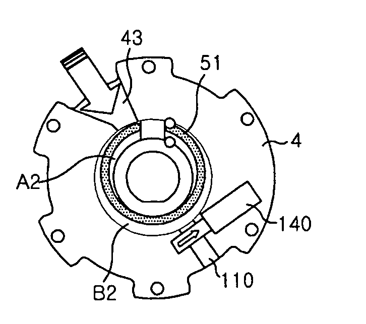
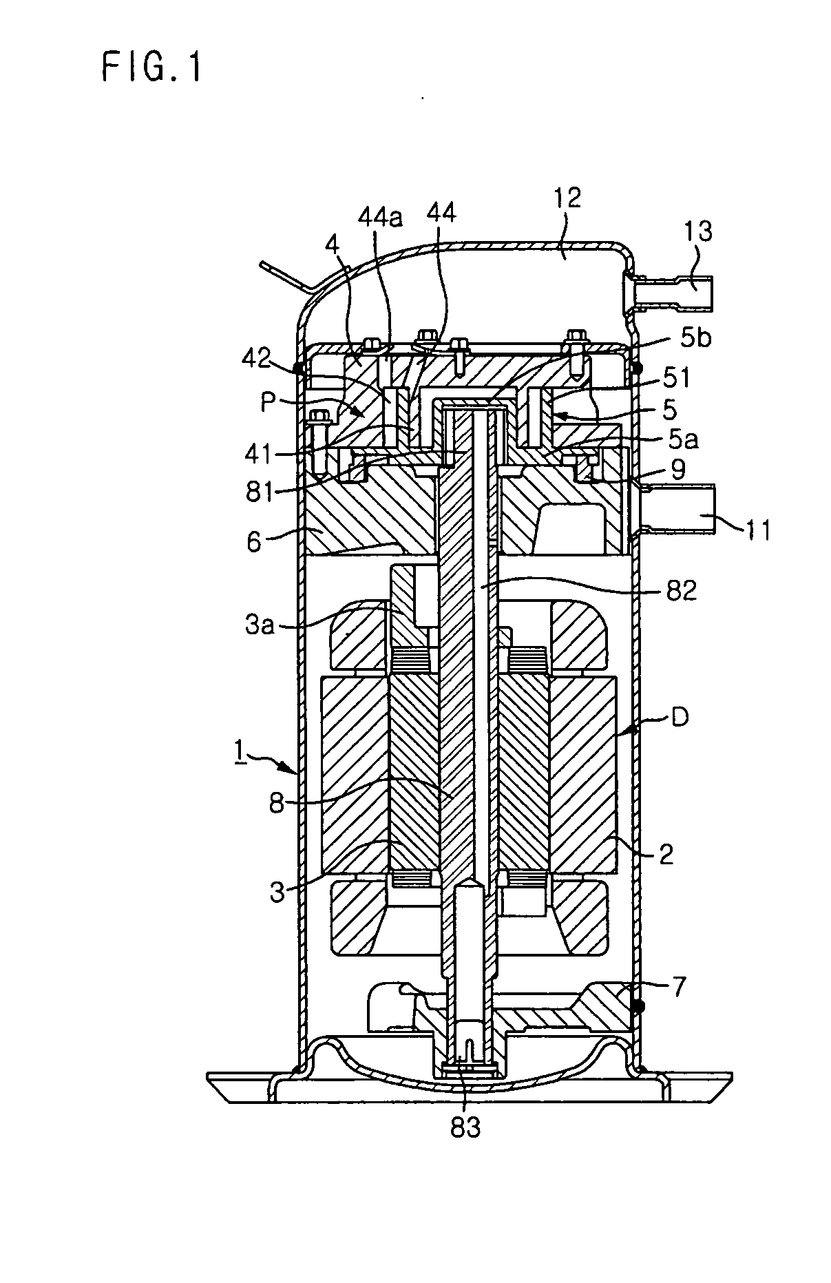
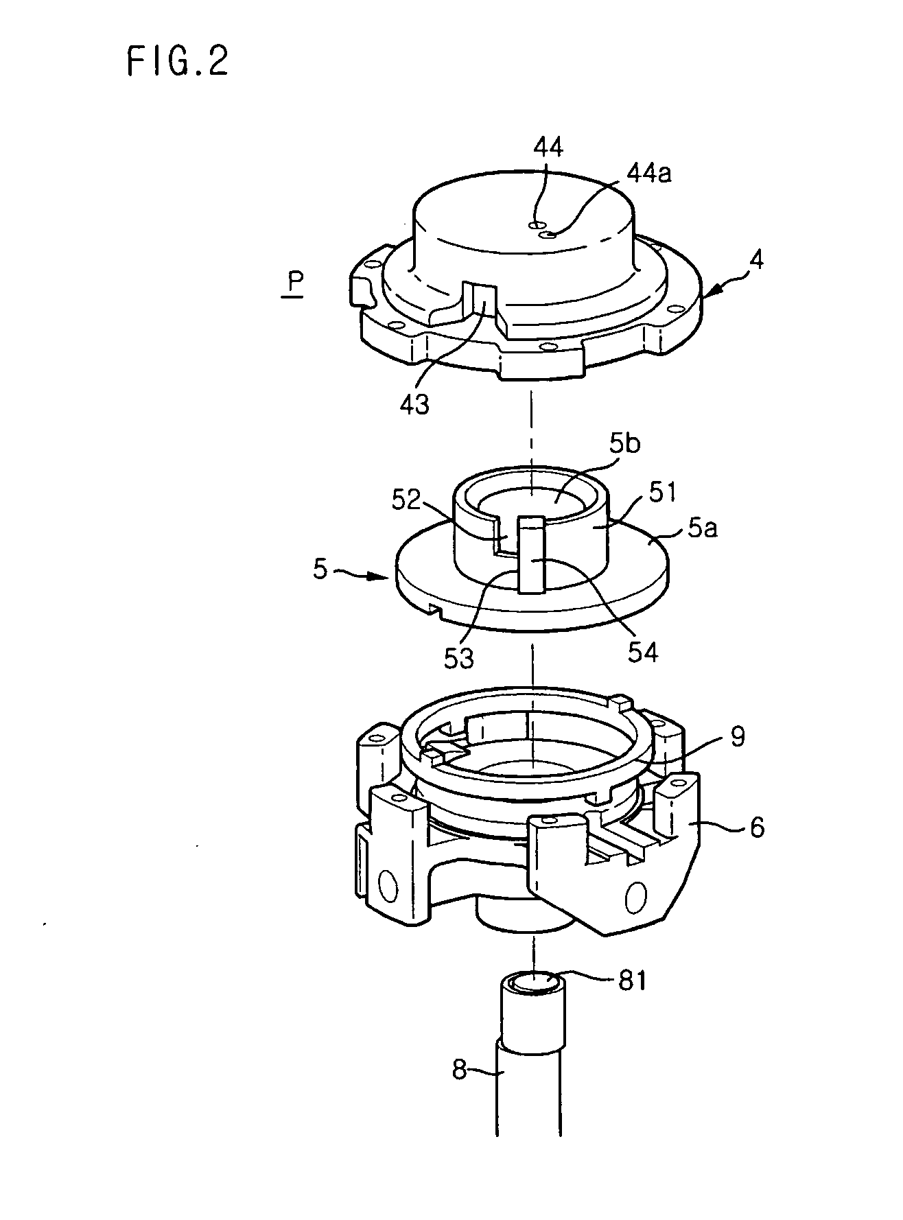
[0048] A compression unit P of the orbiting vane compressor comprises an orbiting vane 5 connected to a crankshaft 8. The orbiting vane 5 is disposed on the upper end of a main frame 6, which rotatably supports the upper part of the crankshaft 8. A cylinder 4, which is attached to the main frame 6, is disposed above the orbiting vane 5. The cylinder 4 is provided at a predetermined position of the circumferential part thereof with an inlet port 43. Inner and outer outlet ports 44 and 44a are formed at predetermined positions of the upper end of the cylinder 4.

[0049] At a predetermined position of the circumferential part of a circular vane 5...


PUM


Abstract

Disclosed herein is a capacity-changing unit disposed in an orbiting vane compressor, which compresses refrigerant gas introduced into a cylinder through an orbiting movement of an orbiting vane in the cylinder, for easily changing capacity of the orbiting vane compressor in a mechanical bypass fashion. The capacity-changing unit comprises a bypass channel communicating with an outer compression chamber formed in the cylinder, and a bypass valve disposed on the bypass channel for opening and closing the bypass channel. According to the present invention, the orbiting vane compressor is selectively operated not only in normal operation mode where compression is performed in an inner compression chamber as well as the outer compression chamber but also in economic operation mode where compression is performed only in the inner compression chamber.

Description

BACKGROUND OF THE INVENTION [0001] 1. Field of the Invention [0002] The present invention relates to an orbiting vane compressor, and, more particularly, to a capacity-changing unit disposed in an orbiting vane compressor, which compresses refrigerant gas introduced into a cylinder through an orbiting movement of an orbiting vane in the cylinder, for easily changing capacity of the orbiting vane compressor in a mechanical bypass fashion without interrupting the operation of the orbiting vane compressor. [0003] 2. Description of the Related Art [0004] Generally, an orbiting vane compressor has inner and outer compression chambers formed in a cylinder through an orbiting movement of an orbiting vane in the cylinder. FIG. 1 is a longitudinal sectional view illustrating the overall structure of a conventional orbiting vane compressor. The conventional orbiting vane compressor shown in FIG. 1 is a hermetically sealed type low-pressure orbiting vane compressor that can be applied to a ref...

Claims


Application Information

Patent Timeline
Patent Type & Authority Applications(United States)
IPC IPC(8): F01C20/18F16N13/20F01C1/063F04C2/00F04C14/18F03C4/00
CPCF04C18/02F04C23/008F04C18/045F04C2270/20F04C28/26F04C18/344F04C18/356
Inventor HWANG, SEON-WOONGYOO, DONG-WON
Owner LG ELECTRONICS INC
Why Eureka
Try Eureka