Pulse Width Modulation System with Pressure Regulating Valve

a technology of pulse width and pressure regulation valve, which is applied in the direction of fluid pressure control, lighting and heating apparatus, instruments, etc., can solve the problems of compressor designer not being able to control the pressure of compressor, compressor failure, damage to compressor, etc., and achieve the effect of increasing the efficiency of the system

Active Publication Date: 2008-10-16
CARRIER CORP
View PDF14 Cites 7 Cited by
  • Summary
  • Abstract
  • Description
  • Claims
  • Application Information

AI Technical Summary

Benefits of technology

[0005]In the disclosed embodiment of this invention, a compressor is associated with a refrigerant system. The refrigerant system has a valve on a suction line leading to the compressor, and a pulse width modulation control is provided for that suction valve. The pulse width modulation control is operable to rapidly cycle the valve between opened and closed positions (states) to change the capacity of the refrigerant system by controlling the amount of refrigerant delivered to the compressor. To increase the efficiency of the system in the pulse width modulation mode it is desirable to have the pressure at the compressor suction to be as low as possible when the valve is in a closed position. However, if the pressure within the compressor shell drops below a certain level, then corona discharge effect may take place leading to a compressor failure. Also, under certain situations, if the suction pressure would drop below a certain value, motor overheating and excessive discharge temperatures may occur damaging the compressor. Thus, the compressor designer's goal is to optimize the system operation such that the suction pressure is maintained as low as possible when the valve is in a closed position but still above the level that prevents these detrimental effects. Further, the compressor designer's objective is to design the system such that for all operating conditions the compressor shell pressure is just above (with some safety margin) the lowest predetermined limit. In the past, the compressor designer could not control this pressure to be just above this lowest pressure limit for all operating conditions. For some of the operating conditions, the pressure was well above the lowest acceptable pressure leading to inefficient operation.

Problems solved by technology

However, if the pressure within the compressor shell drops below a certain level, then corona discharge effect may take place leading to a compressor failure.
Also, under certain situations, if the suction pressure would drop below a certain value, motor overheating and excessive discharge temperatures may occur damaging the compressor.
In the past, the compressor designer could not control this pressure to be just above this lowest pressure limit for all operating conditions.
For some of the operating conditions, the pressure was well above the lowest acceptable pressure leading to inefficient operation.

Method used


Image

  • Pulse Width Modulation System with Pressure Regulating Valve
  • Pulse Width Modulation System with Pressure Regulating Valve

Examples


Embodiment Construction

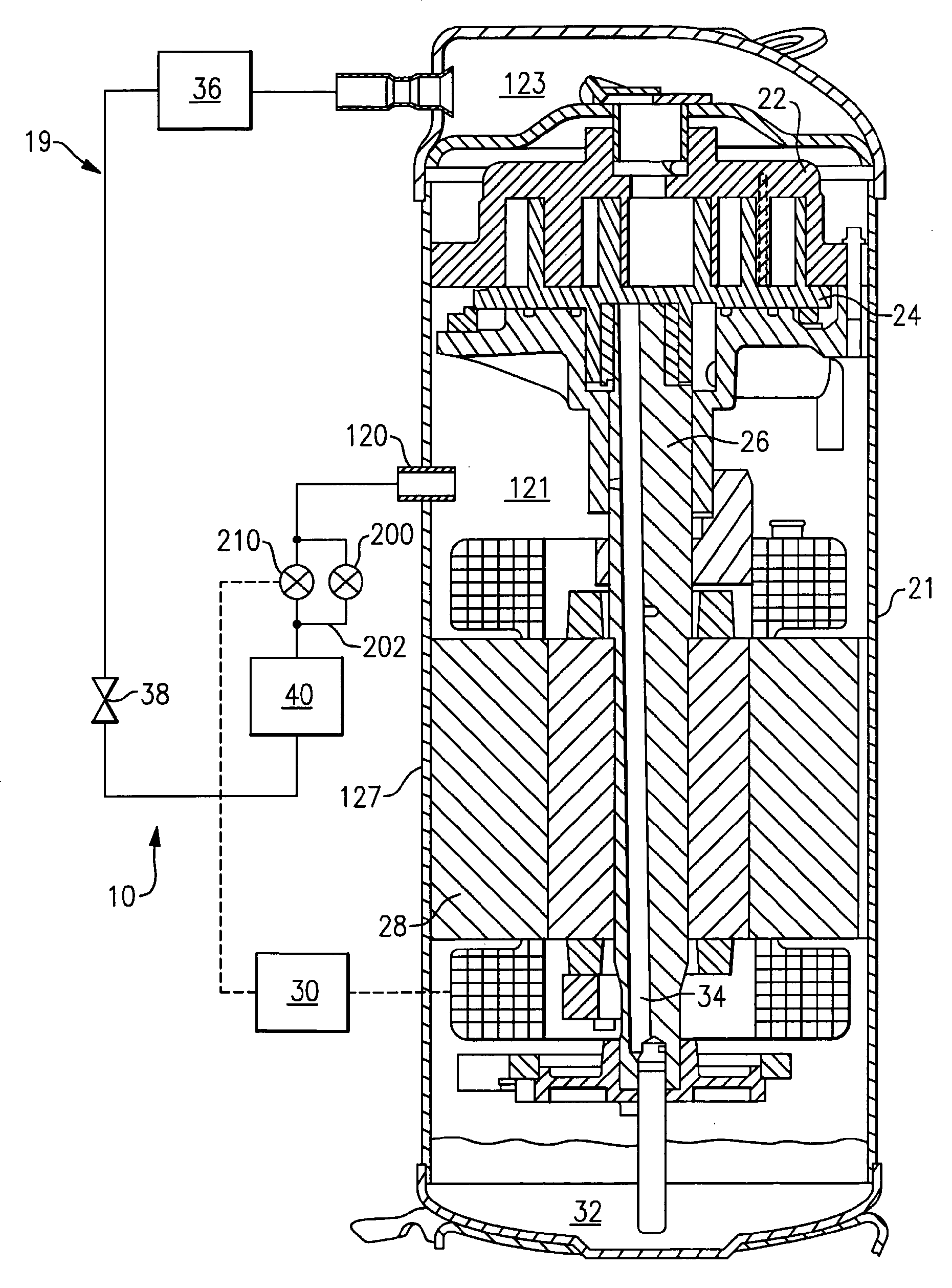
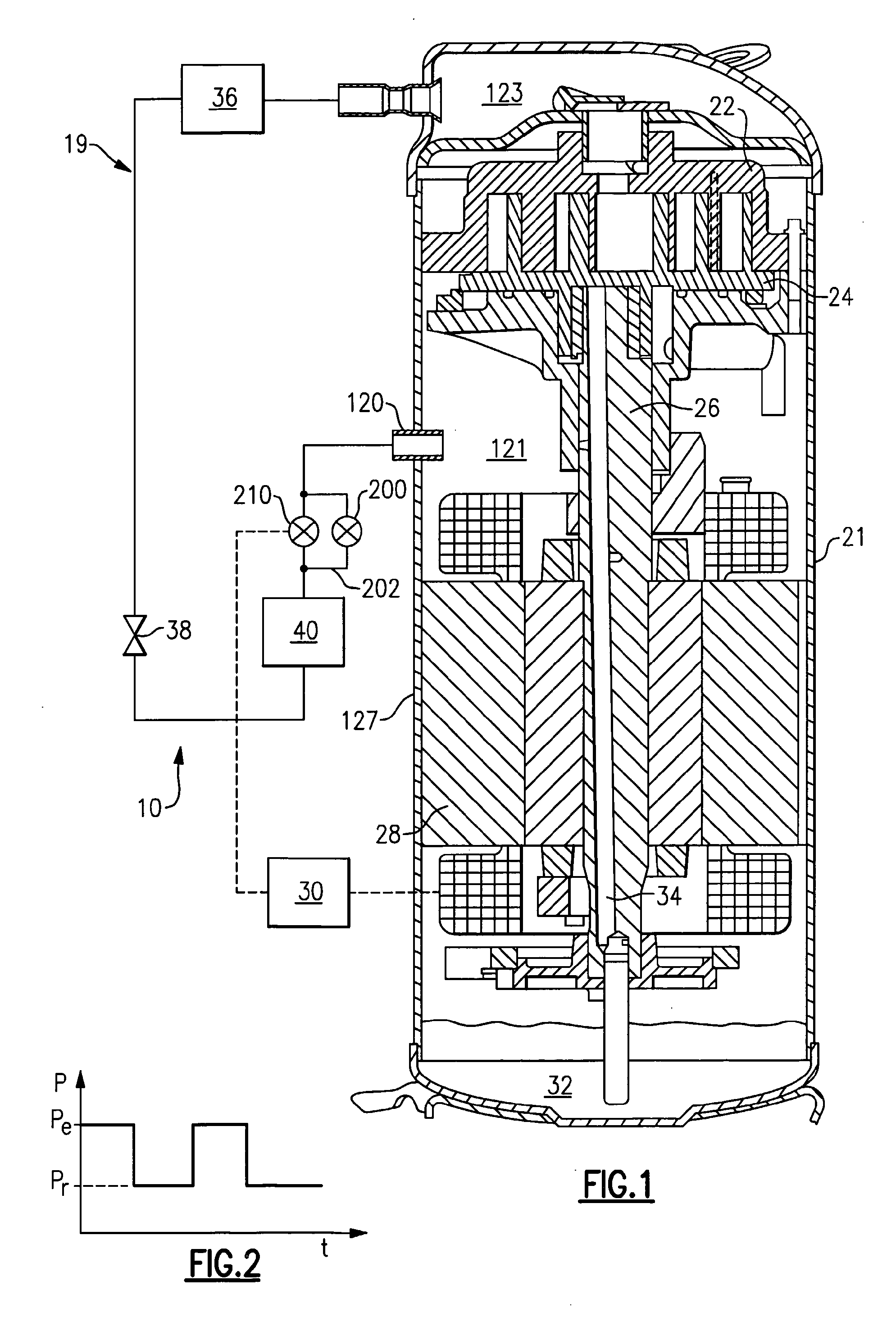
[0012]A refrigerant system 19 is illustrated in FIG. 1 having a scroll compressor 21 incorporating a non-orbiting scroll member 22 and an orbiting scroll member 24. As is known, shaft 26 is driven by an electric motor 28 to cause the orbiting scroll member 24 to orbit. As shown, a control 30 is schematically connected to drive the electric motor 28. An oil sump 32 and an oil passage 34 in the shaft 26 supply oil to the various moving elements in the compressor 21, as known.

[0013]A condenser 36 is positioned downstream of the compressor 21, an expansion device 38 is located downstream of the condenser 36, and an evaporator 40 is positioned downstream of the expansion device 38, as known. As is also known, the compressor 21 is driven by the electric motor 28 to compress a refrigerant and to circulate it through the refrigerant system 19.

[0014]The control 30 may be a microprocessor or other type control that is capable of providing pulse width modulation control to a suction modulation...


PUM


Abstract

A pulse width modulation control is provided for a suction valve on a suction line, delivering refrigerant into a housing shell of a compressor. When the suction valve is closed, the pressure within the housing shell can become very low. Thus, a pressure regulator valve is included within the refrigerant system to selectively deliver a limited amount of refrigerant into the housing shell when the suction valve is closed. The delivery of this limited amount of refrigerant ensures that a specified pressure is maintained within the housing shell to achieve the most efficient operation while at the same time preventing problems associated with damage to electrical terminals, motor overheating and excessive discharge temperature.

Description

BACKGROUND OF THE INVENTION[0001]This application relates to a control for a refrigerant system wherein pulse width modulation technologies are utilized to provide further control over the system operation and wherein a control over a suction pressure is desired when the pulse width modulating valve is in a closed position.[0002]Various operational features are known for providing adjustments in refrigerant system capacity. One approach, which has been utilized in the prior art to change the capacity of a refrigerant system, is the use of pulse width modulation to control valves such as a shutoff valve on a compressor suction line. By rapidly cycling these valves utilizing pulse width modulation techniques, additional capacity control is provided. A system with a pulse width modulating valve will perform most efficiently (in other words, the compressor will consume less power for the same delivered capacity) if the pressure inside the compressor shell within the suction region is re...

Claims


Application Information

Patent Timeline
Patent Type & Authority Applications(United States)
IPC IPC(8): F25B41/04F25B49/00F16K31/02
CPCF04B49/225F04C18/0207F04C23/008G05D16/2013F25B41/043F25B2600/2519F04C28/24F25B41/22G05D16/2022
Inventor LIFSON, ALEXANDERTARAS, MICHAEL F.
Owner CARRIER CORP
Why Eureka
Try Eureka