Pressure sensor and its manufacturing method

A technology of pressure sensor and sensing element, applied in the direction of measuring fluid pressure, measuring fluid pressure through electromagnetic elements, instruments, etc., can solve the problems of connector part size and shape limitation, difficulty, increase capacitor installation area, etc.

Inactive Publication Date: 2003-10-15
DENSO CORP
View PDF0 Cites 8 Cited by
  • Summary
  • Abstract
  • Description
  • Claims
  • Application Information

AI Technical Summary

Problems solved by technology

Therefore, when the capacity of the capacitor 300 is increased in order to improve EMC resistance, the capacitor 300 will be difficult to mount.
Usually, in order to connect with external connectors, the size

Method used


Image

  • Pressure sensor and its manufacturing method
  • Pressure sensor and its manufacturing method
  • Pressure sensor and its manufacturing method

Examples


Embodiment Construction

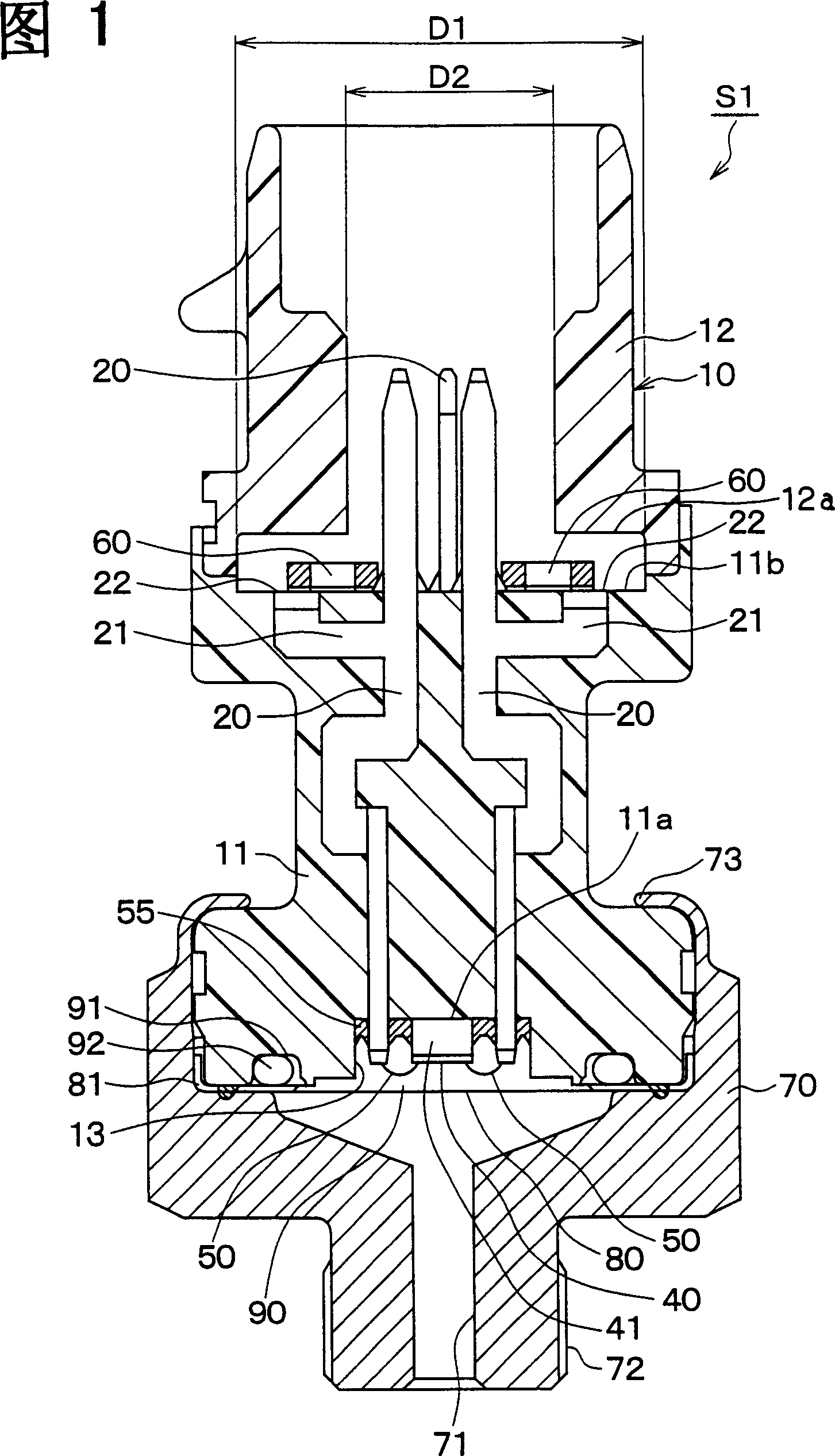
[0022] Preferred embodiments of the present invention will now be described with reference to the accompanying drawings. In this preferred embodiment, the pressure sensor S1 shown in FIG. 1 is generally used to detect the refrigerant pressure in an air conditioner installed in, for example, a vehicle.

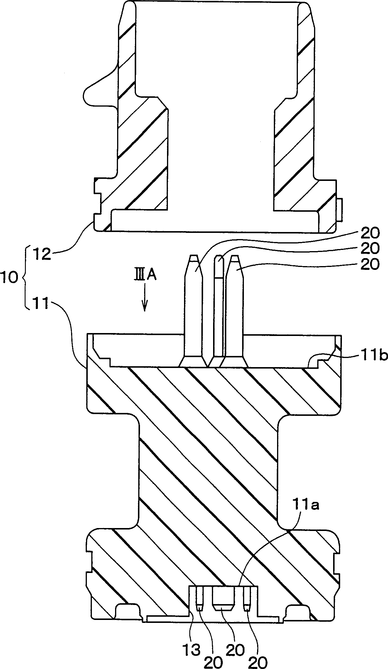
[0023] Pressure sensor S1 contains figure 2 The housing part 10 is shown. figure 2 Shown is the case when the housing part 10 is separated, and the housing part is now divided into a first housing 11 and a second housing 12 . As shown in FIGS. 1 and 2 , the case member 10 is constructed by assembling a first case 11 and a second case 12 together. Both the first case 11 and the second case 12 are integrally molded by one-step molding using a resin such as polyphenylene sulfide (PPS) or polybutylene terephthalate (PBT).

[0024] The first housing 11 is shaped into an approximately cylindrical shape with a stepped portion. A groove portion 13 is formed in one end of the first ...


PUM


Abstract

In a pressure sensor, a sensor element is mounted on a side of a first surface of a first case, and a second case having a cylindrical hollow portion is bonded to the first case to cover a part of a second surface of the first case, opposite to the first surface. Terminals are embedded in the first case to protrude from the second surface, and branch portions are branched from the terminals from an embedded portion in the first case to have exposed portions exposed to the second surface. A chip capacitor is mounted on the exposed portions on the second surface to be electrically connected to the exposed portions. In the pressure sensor, a diameter (D1) of the second surface of the first case is larger than an inner diameter (D2) of the hollow portion at a position where protrusion top ends of the terminals are positioned.

Description

technical field [0001] The invention relates to a pressure sensor comprising a sensing element housed in a housing having terminals for electrically connecting the sensing element to the outside. In particular, the pressure sensor includes a capacitor for improved electromagnetic compatibility (EMC) resistance. Background technique [0002] A pressure sensor described in Japanese Patent JP-A-7-243926 includes a sensing element for detecting pressure and a case housing the sensing element. Within the housing are terminals for electrically connecting the sensing element to the outside. However, in this pressure sensor, due to the radiation of electromagnetic waves, a spurious current can be easily applied to the sensing element, so that the sensing element performs erroneous operations. That is, EMC resistance is lowered. [0003] To overcome this problem, capacitors that limit the spurious current are usually installed in the circuit of the semiconductor chip used to const...

Claims


Application Information

Patent Timeline
IPC IPC(8): G01L9/00
CPCG01L19/142G01L19/0084G01L19/0645
Inventor 竹菴宪治黑田道毅宫川治彦
Owner DENSO CORP
Why Eureka
Try Eureka