Oil-pressure controlling device for earthmoving machine

a technology of oil pressure control and earthmoving machine, which is applied in the direction of servomotors, servomotor components, constructions, etc., can solve problems such as affecting operability, and achieve the effects of reducing discomfort for operators, reducing operating costs, and reducing operating costs

Active Publication Date: 2005-09-20
KOMATSU LTD
View PDF5 Cites 8 Cited by
  • Summary
  • Abstract
  • Description
  • Claims
  • Application Information

AI Technical Summary

Benefits of technology

[0024]With the foregoing problems in view, it is an object of the present invention, without increasing the complexity of the device constitution and at low cost, to alleviate the sense of discomfort that has its origin in the difference in blade operating speeds when a changeover is made between a dual tilt operation and a single tilt operation and, accordingly, to improve operability, by producing the optimum pump flow for both dual tilt operations and single tilt operations.
[0101]Accordingly, based on the sixth invention, the magnitude of the pressure differential set value can be changed in accordance with the work mode which facilitates an improvement in work efficiency, the capacity for changes in cylinder size to be dealt with without replacing the directional flow control valves, and the suppression of production costs and device amendment and improvement costs.

Problems solved by technology

Accordingly, a problem arises in that, when the operator operates the operating lever during the course of the work to perform a changeover from a dual tilt operation to a single operation (or the reverse changeover thereof), a sense of discomfort that has its origin in the difference in blade 3 operating speed is felt by the operator which, from the viewpoint of adjustments to the operation of the operating lever and so on, affects operability.

Method used


Image

  • Oil-pressure controlling device for earthmoving machine
  • Oil-pressure controlling device for earthmoving machine
  • Oil-pressure controlling device for earthmoving machine

Examples


first embodiment

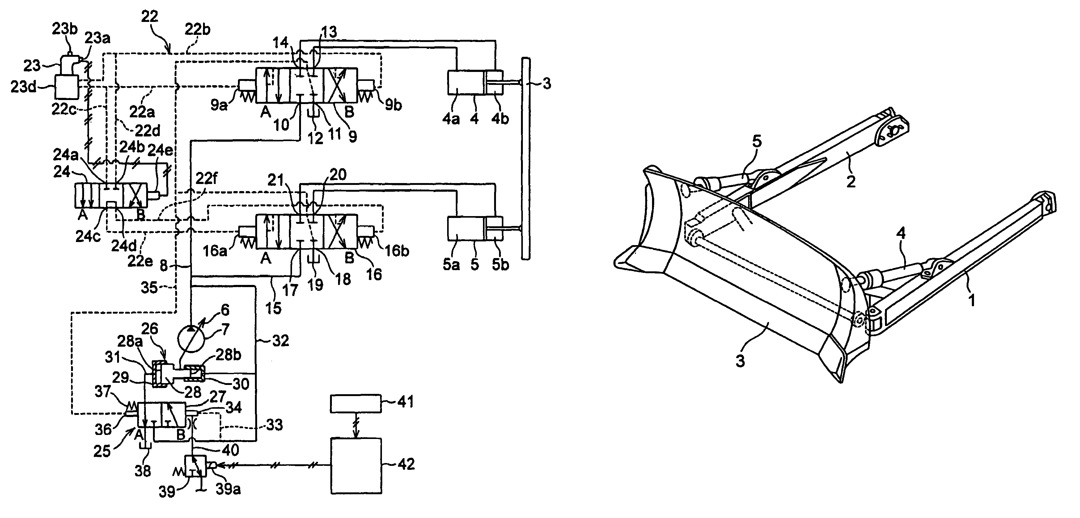
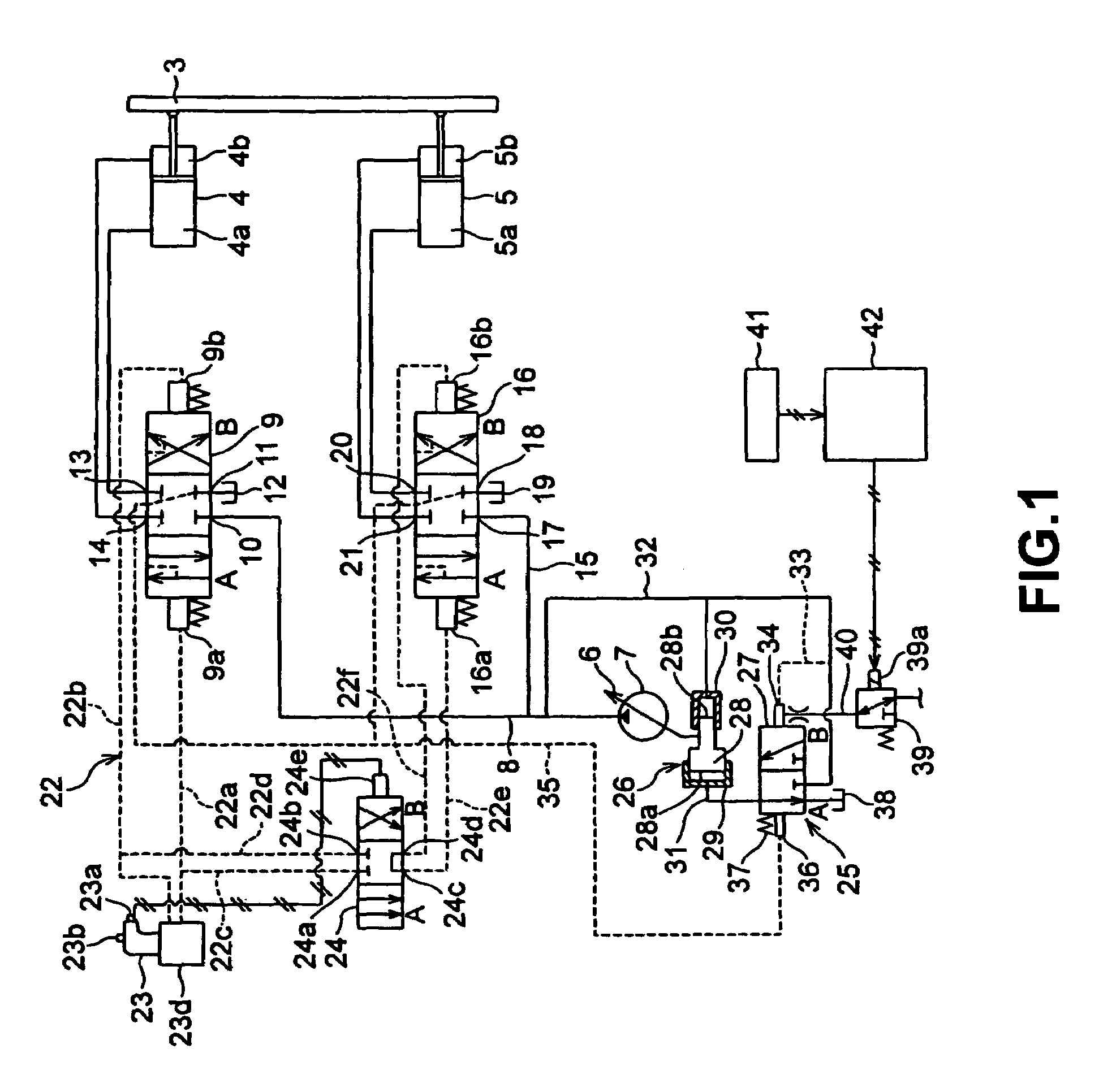
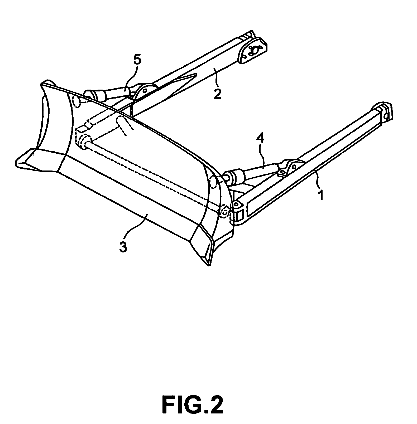
[0110]FIG. 1 is a diagram of the present invention. In FIG. 1, an oil-pressure controlling device for a bulldozer is illustrated using a hydraulic circuit diagram. FIG. 2 is a perspective view of the constitution of the peripheral parts of the bulldozer blade.

[0111]As shown in FIG. 2, a blade 3 is provided in the front part of the vehicle main body not shown in the diagram. That is to say, in the left and right outer side of a truck frame not shown in the diagram, one end of a left and right pair of straight frames 1, 2 are supported using trunnions as a fulcrum. The front ends of the straight frames 1, 2 are pivotally-supported at positions to the left and right respectively of the rear surface of the blade 3.

[0112]A pair of left and right tilt cylinders (tilt hydraulic actuators) 4, 5 that tilt the blade 3 to the left and right are provided between the blade 3 and the straight frames 1, 2. Rods of the tilt cylinders 4, 5 connect to the left and right of the rear surface of the bla...

second embodiment

[0191]Next, a description will be given of a

[0192]Although, in the first embodiment described above, switches for the selection of either a single tilt operation or a dual tilt operation are provided as an indicating device 41 (switches 141a, 141b) separately to switches 23b, 23a (dual tilt operation when switch 23b is OFF, and single tilt operation when switch 23b is OFF and switch 23a is OFF) of the operating lever 23, an embodiment that, interlinked with the operation of the switches 23b, 23a of the operating lever 23 and omitting the arrangement of the indicating device 41, affords the same changes in the magnitude of the ΔPLS as the first embodiment is also possible.

[0193]FIG. 3 is a hydraulic circuit diagram of a second embodiment.

[0194]In FIG. 3, in which the arrangement of the indicating device 41 is omitted, electrical signals that express the operation details of the pitch dump / pitch back switch 23a and the dual switch 23b are sent to the controller 42 by way of an electri...

third embodiment

[0201]Next, a description will be given of a third embodiment ideal for use where left and right cylinders 4, 5 of different cylinder size for machine types of a standard blade specification and machine types of a large blade specification are installed in the hydraulic circuit.

[0202]The constitution of the hydraulic circuit adopted for this third embodiment comprises, replacing the indicating device 41 of the hydraulic circuit of FIG. 1, an indicating device 241 shown in FIG. 6B.

[0203]As shown in FIG. 6B, the indicating device 241, which comprises a switch 241a that is selected for tilt cylinders 4, 5 of a “small cylinder size” and a switch 241b that is selected for tilt cylinders 4, 5 of a “large cylinder size”, is selectively operated by the operator. The indicating device 241 is connected to the controller 42 by way of an electrical signal line. The controller 42 is contacted to an electromagnetic solenoid 39a of a load sensing set pressure changeover valve 39 by way of an elect...


PUM


Abstract

An optimal pump flow for both dual tilt operations and single tilt operations is obtained at low cost without increasing the complexity of the device constitution. Where there is a wish to implement a dual tilt operation, a switch is selectively operated and, in accordance with this selection result, the differential pressure set value decreases and a comparatively small flow is supplied from the hydraulic pump to the left and right tilt cylinders. Accordingly, the extension / retraction speed of the left and right tilt cylinders decreases. Where there is a wish to implement a single tilt operation, a switch is selectively operated and, in accordance with this selection result, the differential pressure set value increases and a comparatively large flow is supplied from the hydraulic pump to the left cylinder. Accordingly, the extension / retraction speed of the left tilt cylinder increases. In this way, the tilt operating speed of the blade in dual tilt operations is made to be the same as the tilt operating speed of the blade in single tilt operations. By virtue of this, when a changeover is implemented from a dual tilt operation to a single tilt operation (or when the reverse changeover thereto is implemented), the operating speed of the blade 3 is unaltered and the discomfort associated with the alteration of the operating speed when this changeover is implemented can be alleviated. Accordingly, the operability throughout the working of the bulldozer is markedly improved.

Description

BACKGROUND OF THE INVENTION[0001]1. Field of the Invention[0002]The present invention relates to an oil-pressure controlling device for an earthmoving machine that performs a load sensing control in which the pressure differential between the discharge pressure of a hydraulic pump and the load pressure of hydraulic actuators are maintained at a set value.[0003]2. Description of the Related Art[0004]FIG. 2 is a perspective view of the peripheral parts of a blade provided in the front part of the chassis of a bulldozer.[0005]The bulldozer carries out work including the digging and shifting of earth as well as the leveling of the ground surface following digging using a blade 3 (moldboard) attached to the front part of the vehicle main body.[0006]A left and right pair of tilt cylinders 4, 5 are provided between the blade 3 and the vehicle main body.[0007]When the two tilt cylinders 4, 5 are simultaneously extension-driven in the same direction the blade 3 is moved to either a pitch dum...

Claims


Application Information

Patent Timeline
Patent Type & Authority Patents(United States)
IPC IPC(8): E02F3/76E02F3/85E02F9/22
CPCE02F3/7618E02F9/2235
Inventor SUZUKI, KAZUYUKITAKAURA, TAKESHI
Owner KOMATSU LTD
Why Eureka
Try Eureka