
Backflow preventer

Inactive Publication Date: 2006-04-13
WATTS REGULATOR
View PDF11 Cites 15 Cited by
  • Summary
  • Abstract
  • Description
  • Claims
  • Application Information

AI Technical Summary

Benefits of technology

[0012] The backflow preventer constructed in accordance with the principles of the present invention offers more flexibility and compatibility with different situation by enabling a user to easily modify or fine tune certain aspects of the preventer to achieve a desired result. For example, modifications can be made to the profile of hump, the number of retention balls used, the geometry or material of retention balls, the geometry or material of o-rings or springs supporting retention balls in recesses, and/or changing the angled relationship between recesses housing the r

Problems solved by technology

Clean water supplies can become contaminated by hazardous connections to the piping system known as cross-connection.
However, when used in, for example, a dom

Method used


Image

  • Backflow preventer
  • Backflow preventer
  • Backflow preventer

Examples


Example

[0022] Presented herein is an improved backflow preventer that provides the ability to easily fine tune its components to achieve a desired, predictable relationship between the amount of friction loss during opening and the distance the valve guide travels during opening and closing.

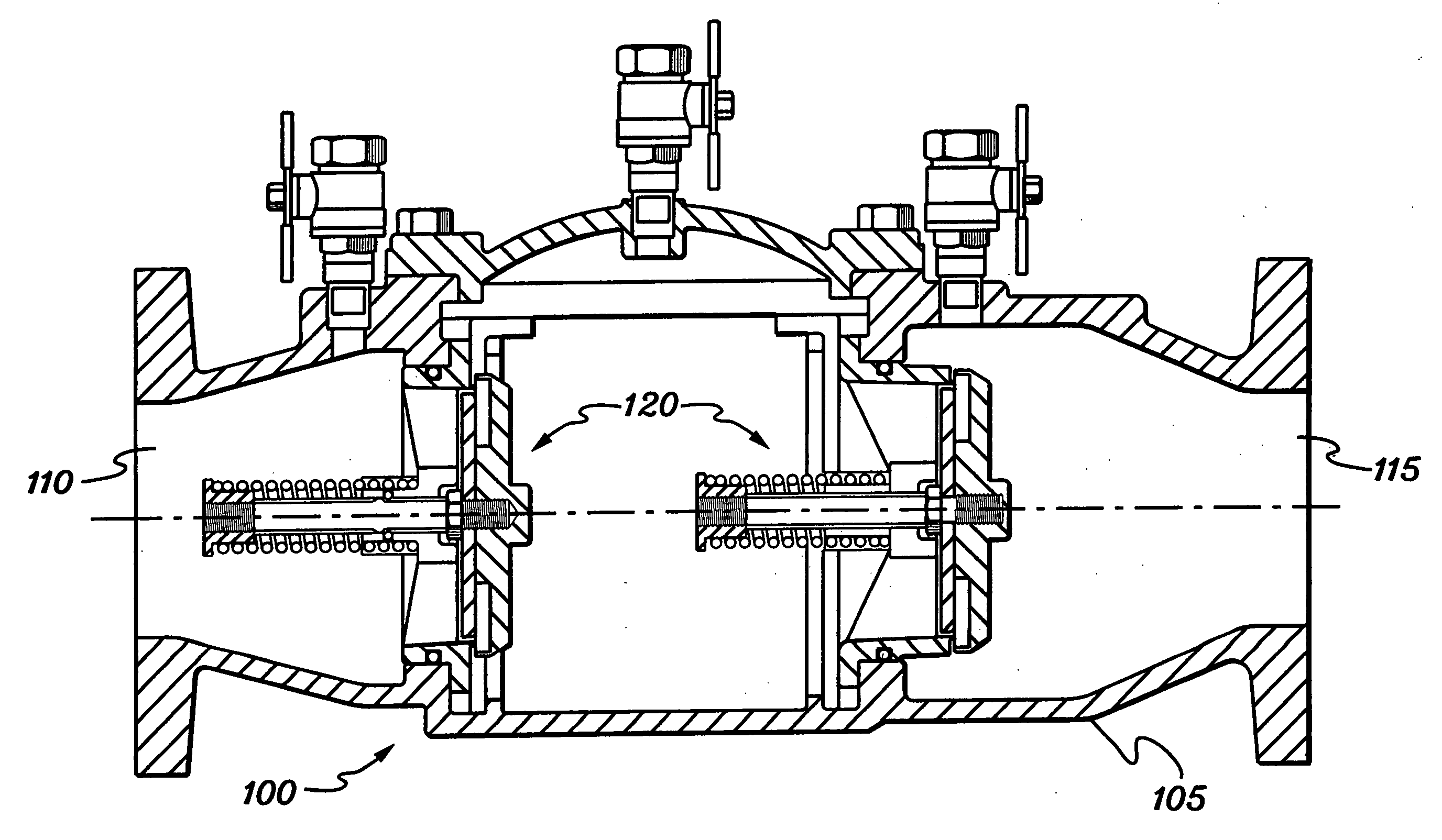
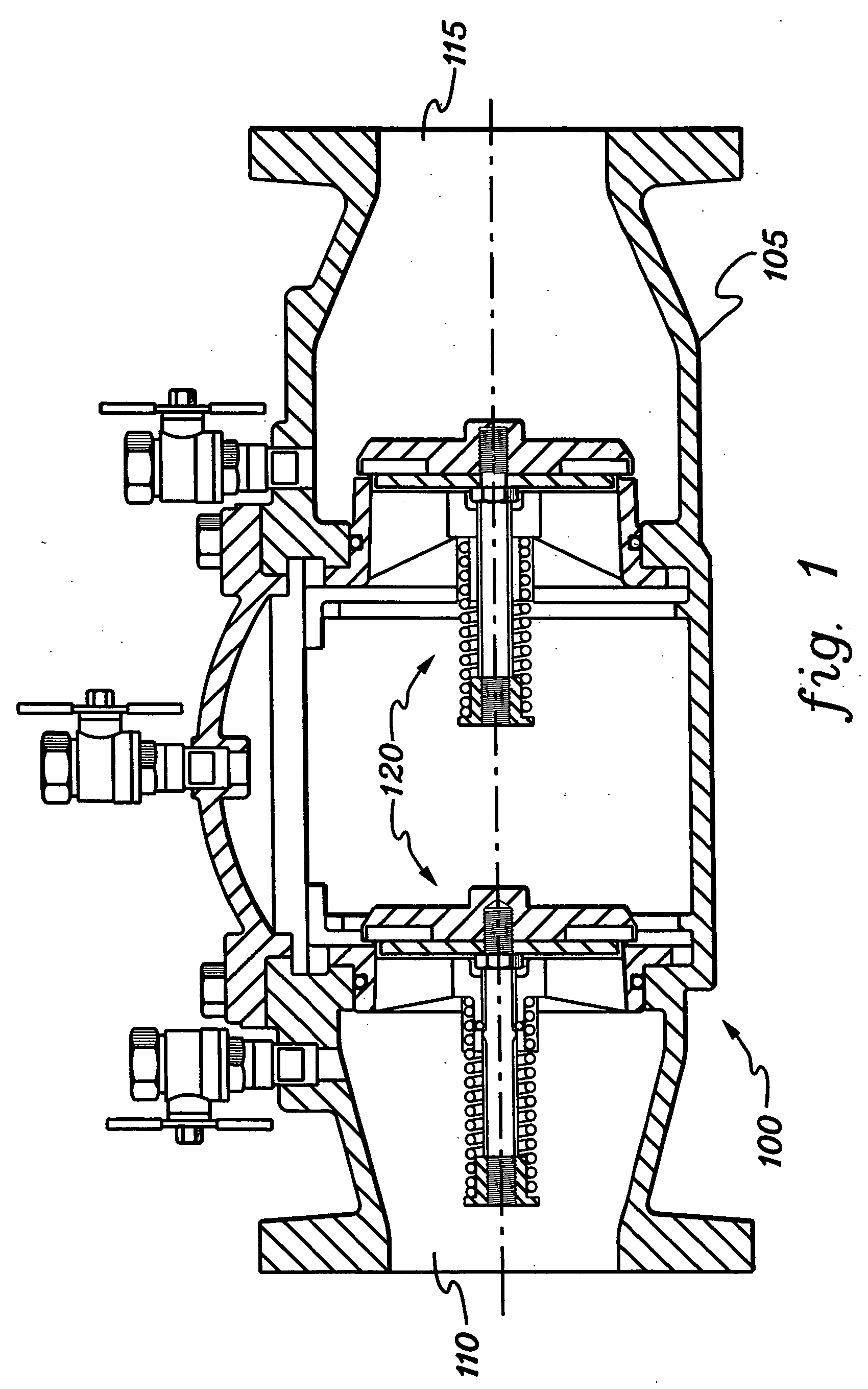
[0023] Referring to FIG. 1, a backflow preventer in accordance with the principles of the present invention includes a housing 105 having an inlet port 110 and an outlet port 115 that define the beginning and end of a water flow path though housing 10S. A pair of check valves 120 is located within housing 105 between inlet and outlet ports 110,115 to permit fluid flow from inlet port 110 to the outlet port 115 while preventing fluid flow in the reverse direction.

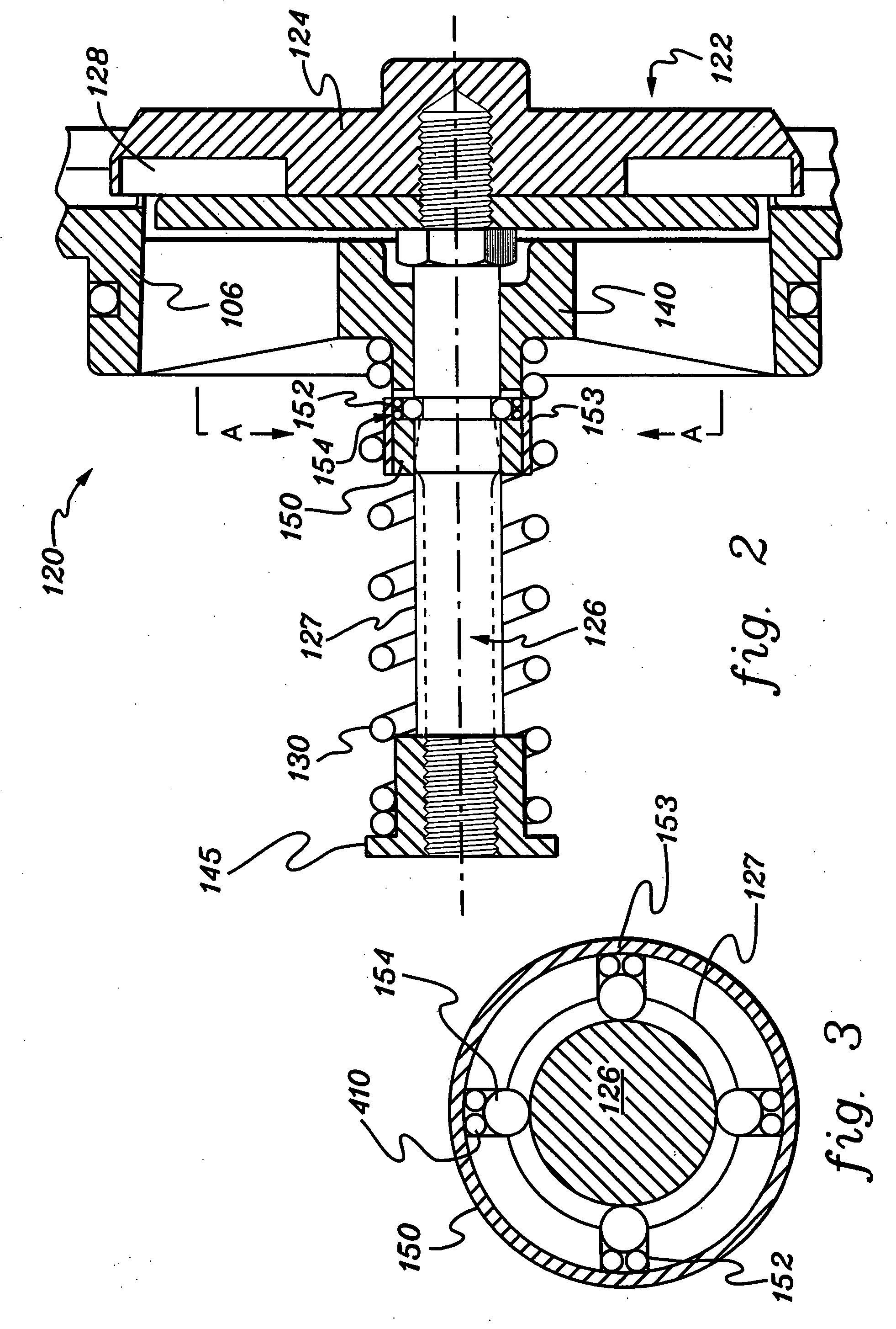
[0024] A check valve constructed in accordance with the principles of the present invention is generally shown in FIG. 2. Each check valve 120 includes a valve plunger 122 including a head 124 and a center stem 126. Plunger head 124 mates with...


PUM


Abstract

A backflow assembly including a housing with a passage having at least one check valve positioned therein to permit fluid flow in one direction while preventing fluid flow in the reverse direction. The check valve includes a valve head connected to a stem having an outer surface. A hump extends radially outward from the outer surface of the stem. The stem is guided by a bushing during opening and closing of the valve. The bushing includes at least one retention member that moves along the outer surface of the stem during opening and closing of the valve. The interaction between the retention member and the hump on the outer surface of the stem causes a higher friction loss during opening and closing of the valve than other portions of the outer surface.

Description

FIELD OF INVENTION [0001] The present invention relates generally to a backflow preventer and check valve construction. More specifically, the invention relates to a valve assembly positioned within backflow preventers installed in water lines to prevent pollution of water supply systems during backflow conditions. BACKGROUND OF THE INVENTION [0002] Clean water supplies can become contaminated by hazardous connections to the piping system known as cross-connection. A cross-connection is a connection between a drinking water plumbing system and any other source that may contribute to the degradation of the quality of drinking water. [0003] A backflow preventer is typically used to prevent contamination of a main water supply line by reducing or eliminating backflow of contaminated water into the supply line. A backflow preventer is installed in, for example, a pipeline between a main water supply line and a service line and designed to protect, for example, drinking water plumbing sy...

Claims


Application Information

Patent Timeline
IPC IPC(8): F16K15/06
CPCF16K15/063F16K15/066Y10T137/7838Y10T137/7931Y10T137/7932
Inventor ANDERSSON, BO
Owner WATTS REGULATOR
Learn More