
Wire collision sensor system

a collision sensor and wire technology, applied in the direction of roofs, pedestrian/occupant safety arrangements, vehicular safety arrangements, etc., can solve the problems of deteriorating sensing accuracy and disadvantage of sensing latency

Inactive Publication Date: 2006-04-13
DENSO CORP
View PDF19 Cites 7 Cited by
  • Summary
  • Abstract
  • Description
  • Claims
  • Application Information

AI Technical Summary

Benefits of technology

[0007] The present invention addresses the above disadvantages. Thus, it is an objective of the present invention to provide a wire collision sensor system, which effectively senses a collision or a collision load of a collision body.

Problems solved by technology

Thus, this may cause a disadvantage, such as deterioration of a degree of sensing accuracy.
Also, there may be a disadvantage of sensing latency.

Method used


Image

  • Wire collision sensor system
  • Wire collision sensor system
  • Wire collision sensor system

Examples


first embodiment

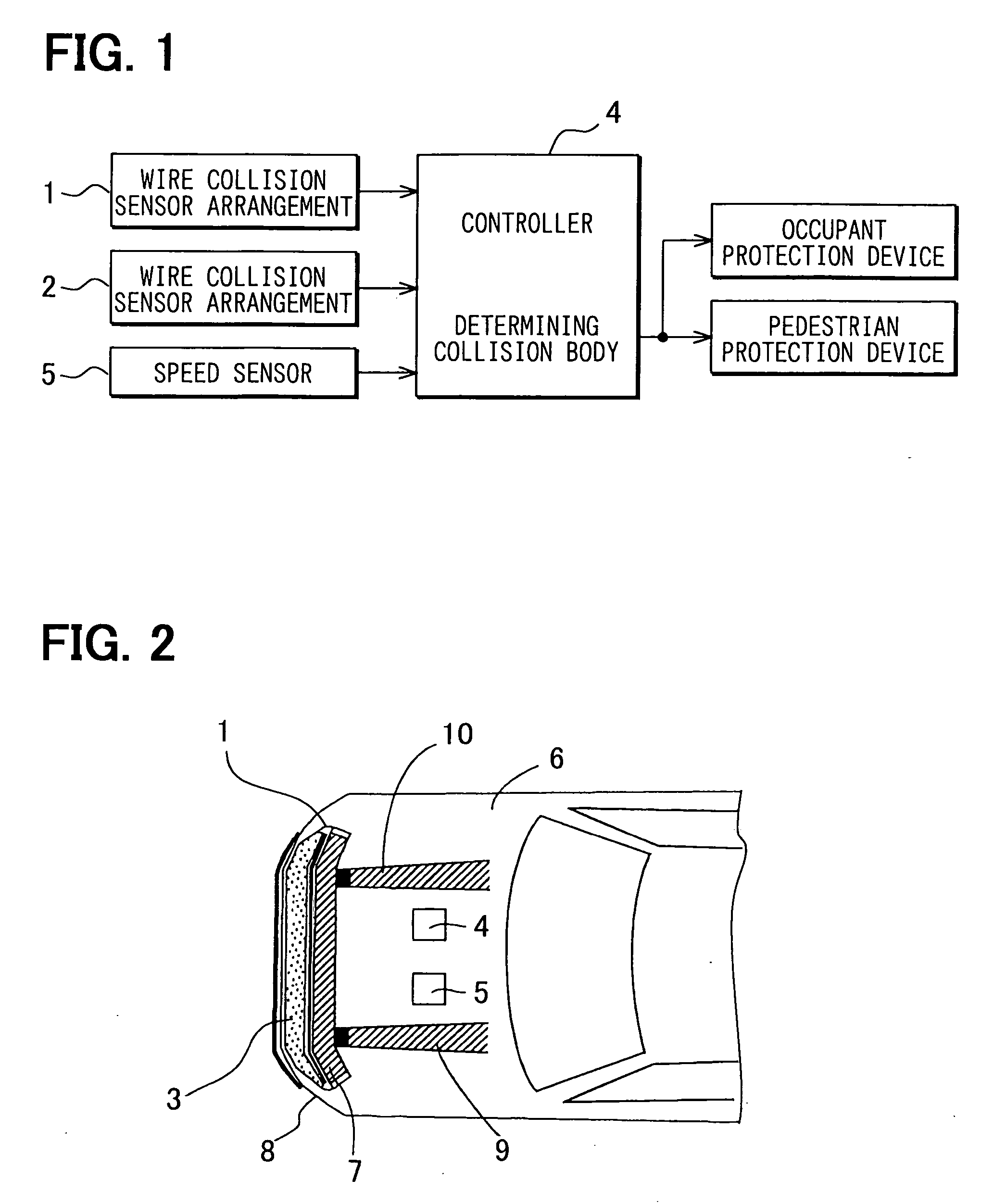
[0015] A wire collision sensor system for a vehicle of a first embodiment will be described with reference to a block diagram shown in FIG. 1 and a schematic plan view shown in FIG. 2. A front direction according to the present embodiment is a driving direction of the vehicle. A widthwise direction according to the present embodiment is a transverse direction of the vehicle.

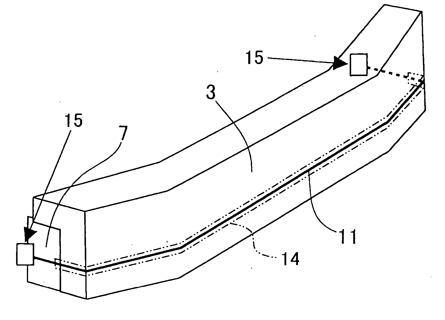
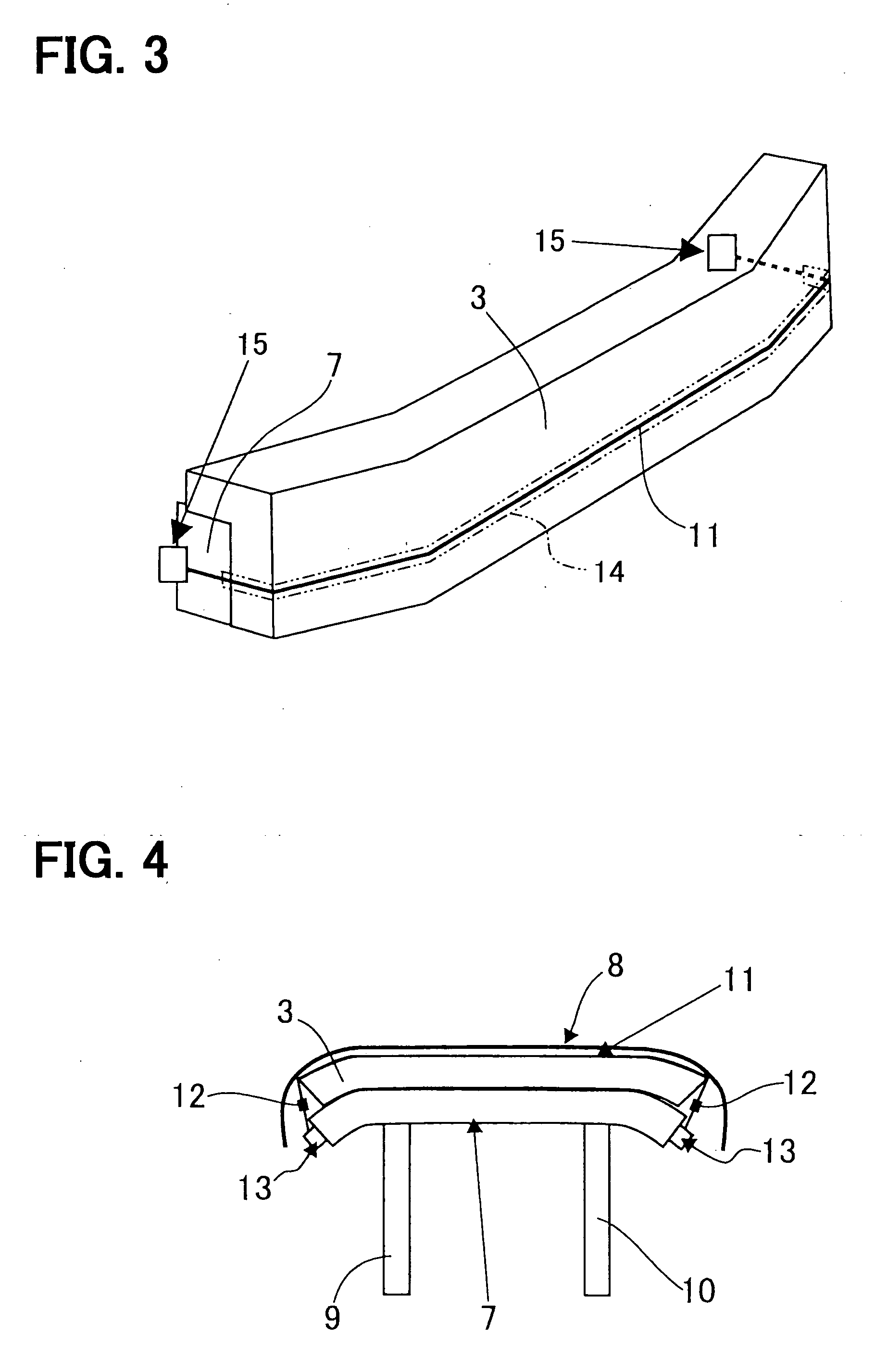
[0016] Numerals 1 and 2 are wire collision sensor arrangements, a numeral 3 is a bumper absorber, a numeral 4 is a controller (a signal processing unit), a numeral 5 is a speed sensor, a numeral 6 is a vehicle body, a numeral 7 is a bumper reinforcement, a numeral 8 is a bumper cover and numerals 9 and 10 are side members. The side members 9, 10 are structural members, which are arranged at a predetermined interval at a bottom part of the vehicle and extend in a longitudinal direction of the vehicle. The bumper reinforcement 7 is a structural member, which is fixed horizontally with front ends of the side member...

second embodiment

[0033] In a second embodiment, similar components of a wire collision sensor system, which are similar to the components of the wire collision sensor system of the first embodiment, will be indicated by the same numerals.

[0034] The second embodiment is characterized by supporting the resin thread 11 of the collision sensor system 1 in a back surface of the bumper cover 8. The bumper cover 8 includes projection members 81, which are arranged at predetermined intervals, and slidably support the resin thread 11. Each projection member 81 is formed into an L-shaped body, which defines a groove that opens upward. The groove supports the resin thread 11. The projection member 81 may be designed to have a hole, which supports the resin thread 11, instead of the groove. This brings an equivalent effect with the first embodiment. Also, the projection members 81, which are arranged at the predetermined intervals for slidably supporting the resin thread 11, may be supported by the bumper abso...


PUM


Abstract

A wire collision sensor system for a vehicle, which includes a vehicle body, includes a bumper, a wire, a wire deformation sensor and a determination circuit. The bumper is mounted on a longitudinal end portion of the vehicle body. The wire, which senses a collision of the vehicle, is received in the bumper and extends along the bumper in a transverse direction of the vehicle. The wire is connected to at least one of the vehicle body and the bumper at both ends in such a manner that the wire is displaceable in a longitudinal direction of the wire. The wire deformation sensor electrically senses a physical quantity, which is associated with a deformation of the wire at a time of the collision. The wire deformation sensor transmits an output, which indicates the sensed physical quantity. The determination circuit determines a state of the collision based on the output.

Description

CROSS REFERENCE TO RELATED APPLICATION [0001] This application is based on and incorporates herein by reference Japanese Patent Applications No. 2004-297747 filed on Oct. 12, 2004. BACKGROUND OF THE INVENTION [0002] 1. Field of the Invention [0003] The present invention relates to a wire collision sensor system for vehicle. The wire collision sensor system senses a vehicle collision load by use of a wire. [0004] 2. Description of Related Art [0005] Unexamined Japanese Patent Publication No. 2004-212281, which corresponds to U.S. 2004 / 0129479 A1, discloses the wire collision sensor system, which senses an increase of a tensile force of a wire at a time of a vehicle collision. The wire is horizontally spanned along a front side of a bumper reinforcement at a predetermined level of the tensile force. [0006] An invention according to the Unexamined Japanese Patent Publication No. 2004-212281 measures a tensile force variation, which is caused by deformation of the bumper reinforcement a...

Claims


Application Information

Patent Timeline
Patent Type & Authority Applications(United States)
IPC IPC(8): B60R21/01
CPCB60R21/0136B60R21/34
Inventor TANABE, TAKATOSHI
Owner DENSO CORP
Learn More