Wireless power transmission apparatus and wireless power transmission method

a technology of wireless power transmission and wireless transmission, which is applied in the direction of transformers, inductances, transportation and packaging, etc., can solve the problem of remarkably low degree of positional freedom, and achieve the effect of efficiently sensed and minimal power consumption

Active Publication Date: 2018-11-27
WILUS INST OF STANDARDS & TECH
View PDF7 Cites 8 Cited by
  • Summary
  • Abstract
  • Description
  • Claims
  • Application Information

AI Technical Summary

Benefits of technology

[0014]According to exemplary embodiments of the present invention, a plurality of standby states for a wireless power transmitting apparatus can be defined and transmission of a weak detector signal and a strong detector signal can be controlled according to each standby state. Therefore, the wireless power transmitting apparatus can minimize power consumption caused due to transmissions of a detector signal.
[0015]According to the exemplary embodiments of the present invention, detector signals for various types of wireless power receiving apparatuses can be defined and therefore, the wireless power transmitting apparatus is compatible with a plurality of types of wireless power receiving apparatuses to transmit wireless power.
[0016]According to the exemplary embodiments of the present invention, an oscillation situation of a power state, a cross connection situation between devices, and the like can be prevented, which can occur at the time of transmitting power to a plurality of wireless power receiving apparatuses.
[0017]According to the exemplary embodiments of the present invention, when a log object is laid in the wireless power transmitting apparatus, the log object can be efficiently sensed.
[0018]According to the exemplary embodiments of the present invention, when the power is transmitted to the plurality of wireless power receiving apparatuses, a charging priority can be set for each receiving apparatus, and as a result, the power transmission can be differentiated for each receiving apparatus.
[0019]According to the exemplary embodiments of the present invention, charging states of multiple wireless power receiving apparatuses which receive the power from one wireless power transmitting apparatus can be verified at once at the time of transmitting the wireless power.

Problems solved by technology

The wireless power transmission technology of the electromagnetic inductive coupling scheme has an advantage that transmission efficiency is high, but has a disadvantage that a power transmission distance is limited to several mm and the wireless power transmission technology is very sensitive to matching of the coils, and as a result, a degree of positional freedom is remarkably low.

Method used


Image

  • Wireless power transmission apparatus and wireless power transmission method
  • Wireless power transmission apparatus and wireless power transmission method
  • Wireless power transmission apparatus and wireless power transmission method

Examples


Embodiment Construction

Technical Problem

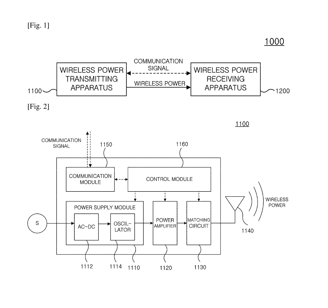
[0009]The present invention has been made in an effort to reduce standby power consumption due to transmission of a weak detector signal and / or a strong detector signal in a standby state of a wireless power transmitting apparatus.

[0010]The present invention has also been made in an effort to provide a method for controlling various situations which can occur when the wireless power transmitting apparatus transmits power to a plurality of wireless power receiving apparatuses.

[0011]The present invention has also been made in an effort to provide a method in which the wireless power transmitting apparatus can efficiently control the plurality of wireless power receiving apparatuses.

Technical Solution

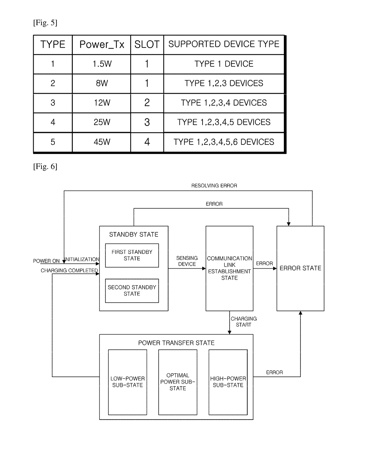
[0012]An exemplary embodiment of the present invention provides a wireless power transmitting method of a wireless power transmitting apparatus, wherein a standby state of determining whether at least one wireless power receiving apparatus is positioned within a wireless c...


PUM

PropertyMeasurementUnit
drive poweraaaaaaaaaa
poweraaaaaaaaaa

Abstract

The present invention relates to a method for verifying a charging state of a wireless power receiving apparatus in the wireless power transmitting apparatus, and more particularly, to an apparatus and a method for efficiently performing and controlling wireless power transmission.To this end, the present invention provides a wireless power transmitting method, wherein a standby state of determining whether at least one wireless power receiving apparatus is positioned within a wireless charge range of the wireless power transmitting apparatus and a power transfer state of transmitting power to the corresponding wireless power receiving apparatus when at least one wireless power receiving apparatus is detected in the standby state are provided, and the standby state includes a first standby state of periodically transmitting a weak detector signal and a strong detector signal and a second standby state in which at least one of a transmission period of the weak detector signal and a transmission period of the strong detector signal is different from that of the first standby state, the method including: determining any one state of the first standby state and the second standby state of the wireless power transmitting apparatus; and transmitting the weak detector signal and the strong detector signal based on the determined standby state, wherein the transmission period of the weak detector signal in the second standby state is longer than the transmission period of the weak detector signal in the first standby state.

Description

CROSS-REFERENCE TO RELATED APPLICATION[0001]This application is the U.S. National Stage of International Patent Application No. PCT / KR 2015 / 000074 filed on Jan. 5, 2015, which claims the priority to Korean Patent Application No. 10-2014-0064245 filed in the Korean Intellectual Property Office on May 28, 2014 and claims the benefit to U.S. Provisional Patent Application No. 61 / 923,240filed on Jan, 3, 2014, the entire contents of which are incorporated herein by reference.TECHNICAL FIELD[0002]The present invention relates to a wireless power transmission apparatus and a wireless power transmission method, and more particularly, to an apparatus and a method for efficiently perform and controlling wireless power transmission.BACKGROUND ART[0003]A wireless power transmission technology is a technology that wirelessly transmits power between a power source and an electronic apparatus. As one example, by using the wireless power transmission technology, a battery of a mobile terminal can b...

Claims


Application Information

Patent Timeline
Patent Type & Authority Patents(United States)
IPC IPC(8): H01F27/42H01F38/00H02J50/12H02J50/80H02J50/50H02J7/00H02J50/60H02J50/90H01F37/00H02J7/02
CPCH02J50/12H02J7/0027H02J7/025H02J50/60H02J50/80H02J50/90H02J50/50Y02T10/7055H02J50/40H04B5/0037H02J50/005Y02T10/70
Inventor SON, JUHYUNGLEE, JAECHANLIM, KUKILKWAK, JINSAMOH, HYUNOH
Owner WILUS INST OF STANDARDS & TECH
Why Eureka
Try Eureka