
Simulated annealing for traffic matrix estimation

a traffic matrix and simulation annealing technology, applied in data switching networks, digital transmission, data processing applications, etc., can solve the problems of large tables, inability to egress from subsets, infeasible for large networks, and large number of packets

Active Publication Date: 2006-04-13
RPX CORP
View PDF6 Cites 19 Cited by
  • Summary
  • Abstract
  • Description
  • Claims
  • Application Information

AI Technical Summary

Benefits of technology

[0014] Advantageously, the invention requires no assumptions about the traffic, i.e. it allows the user to specify prior information about the network and traffic flows in a simple manner.

Problems solved by technology

The new bandwidth consuming applications supported the network traffic growth and the rapid change in equipment utilization confront the network providers with the issue of whether the network has adequate capacity to support the current and the future traffic requirements.
However, all these tools require knowledge of traffic statistics, and more specifically of the real time source-destination traffic demands.
However, this method requires huge tables for recording this information.
Furthermore, if what is desired is a source to destination traffic matrix for a subset of the network, then the ingress into the subset and the egress from the subset will not be available without looking at the source and destination addresses and then determining the path the packet would take as indicated by the routing information.
This would be infeasible for large networks and large numbers of packets.
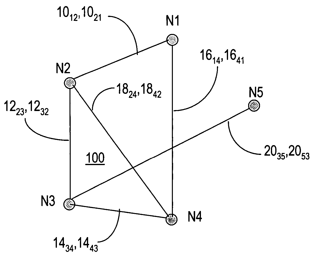
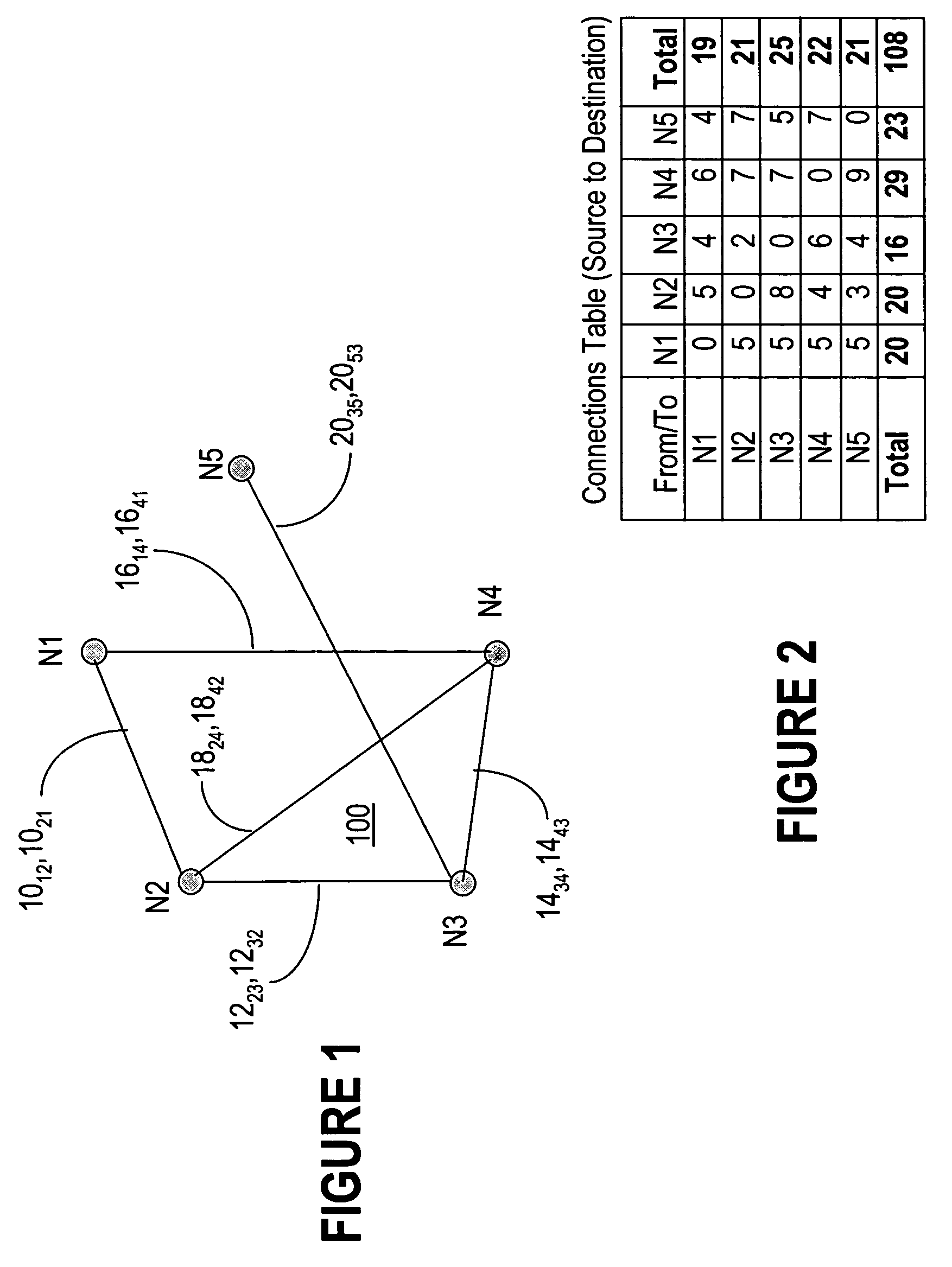
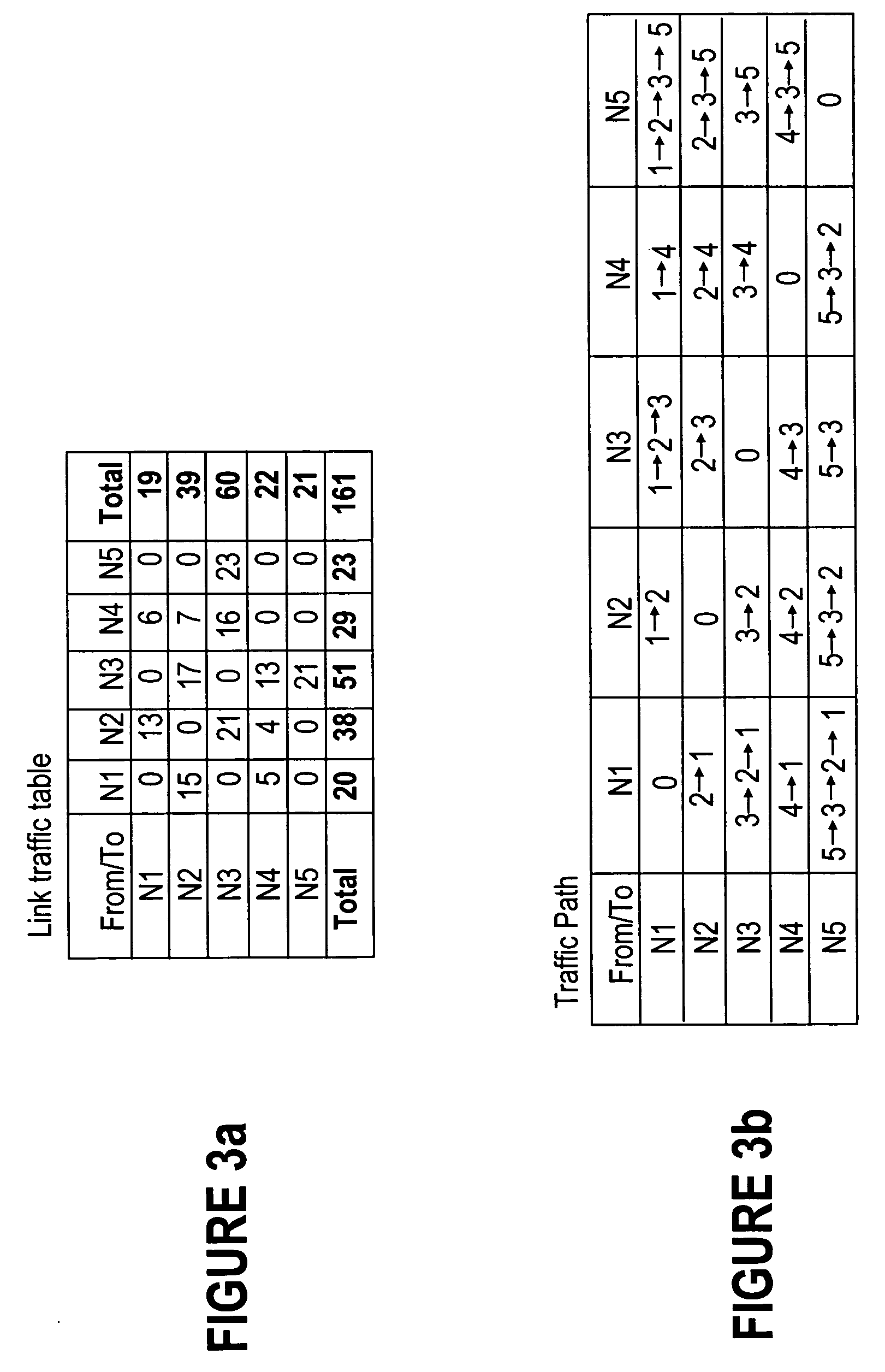
While the current routers are able to measure the counts for the incoming and outgoing traffic at each interface (incoming and outgoing links), it is generally impossible to derive the traffic matrix from the link counts with mathematical certainty.
However, the tomo-gravity method does not allow for easy specification of arbitrary constraints, such as knowing that if a link is twice the speed of another, it probably has roughly twice the traffic.
The prior art techniques described above, such as monitoring all packets and gravity, tomographic approach and tomo-gravity, are not satisfactory for large traffic volumes and rely on unrealistic assumptions, respectively.

Method used


Image

  • Simulated annealing for traffic matrix estimation
  • Simulated annealing for traffic matrix estimation
  • Simulated annealing for traffic matrix estimation

Examples


Embodiment Construction

[0026] Simulated annealing is an optimization technique developed for metallurgical processes, whereby a control parameter is used to model the temperature of an oven during annealing. The control parameter, hence called temperature (T), is set to an initial value and is lowered over time, according to a predetermined schedule.

[0027] Basic simulated annealing is successfully used for example in VLSI physical design, which is explained here in general term for a better understanding of the algorithm. A change to an initial configuration is made by moving a component or interchanging locations of two components; the placement is changed randomly to get a new placement. The control parameter T indicates the probability of accepting moves (shuffles) that result in increased cost. After the shuffle, the cost of the new placement is evaluated and if there is a decrease in cost, the configuration is accepted. Otherwise, the new configuration is accepted with a probability that depends on ...


PUM


Abstract

The SATME method and system estimates source-to-destination traffic matrices using a simulated annealing algorithm, the traffic matrix estimation being represented as a probability distribution over the set of all possible matrices that satisfy a set of given constraints. The constraints explicitly encode information that the user knows about the network traffic as components of an objective function (a fitness function), that is then minimized using simulated annealing. With the method according to the invention, arbitrary constraints of any form can be included, and the case where there are no feasible solutions can be diagnosed by the objective function not converging to zero.

Description

FIELD OF THE INVENTION [0001] The invention is directed to the estimating performance of communication networks and in particular to a simulated annealing method and system for traffic matrix estimation (SATME). BACKGROUND OF THE INVENTION [0002] Spurred by technological advances, the telecommunications industry has experienced tremendous growth over the last decade. The advances in processing power of desktop computers and the decrease in applications response times fostered corresponding improvements in the network infrastructure. The new bandwidth consuming applications supported the network traffic growth and the rapid change in equipment utilization confront the network providers with the issue of whether the network has adequate capacity to support the current and the future traffic requirements. [0003] In any traffic and / or network engineering task, more knowledge about the network can only be beneficial. Specific applications require for example knowledge of how much traffic...

Claims


Application Information

Patent Timeline
IPC IPC(8): H04L12/28
CPCG06Q10/04H04L41/145H04L41/147
Inventor RABINOVITCH, PETERMCBRIDE, BRIAN
Owner RPX CORP
Learn More