Differential device and drive power transmission unit using the same

a technology of differential devices and power transmission units, applied in mechanical devices, transportation and packaging, gearing, etc., can solve the problems of difficult to obtain the larger reduction ratio, difficult to obtain the accuracy of internal teeth machining, and complicated device structure, so as to prevent the expansion of a motor and the effect of precision

Inactive Publication Date: 2006-04-13
JTEKT CORP
View PDF3 Cites 53 Cited by
  • Summary
  • Abstract
  • Description
  • Claims
  • Application Information

AI Technical Summary

Benefits of technology

[0007] This invention aims to provide a differential device capable of assuring the precision and prevented from enlarging a motor and the complicating the structure of the same. This invention also aims to provide a drive power transmission unit using the device.

Problems solved by technology

The differential device disclosed in the aforementioned Patent, however, is provided with a gear of internal teeth type, so that it is required to machine the internal teeth and that the machining of the internal teeth is difficult in obtaining its accuracy.
Thus, a reduction ratio may be set at ⅙ approximately by that reduction mechanism, so that it may be difficult to obtain the larger reduction ratio thereby.
Thus, bearings for supporting the internal gear need to be provided, whereby they cause a problem that the structure of the device is complicated.

Method used


Image

  • Differential device and drive power transmission unit using the same
  • Differential device and drive power transmission unit using the same
  • Differential device and drive power transmission unit using the same

Examples


embodiment 1

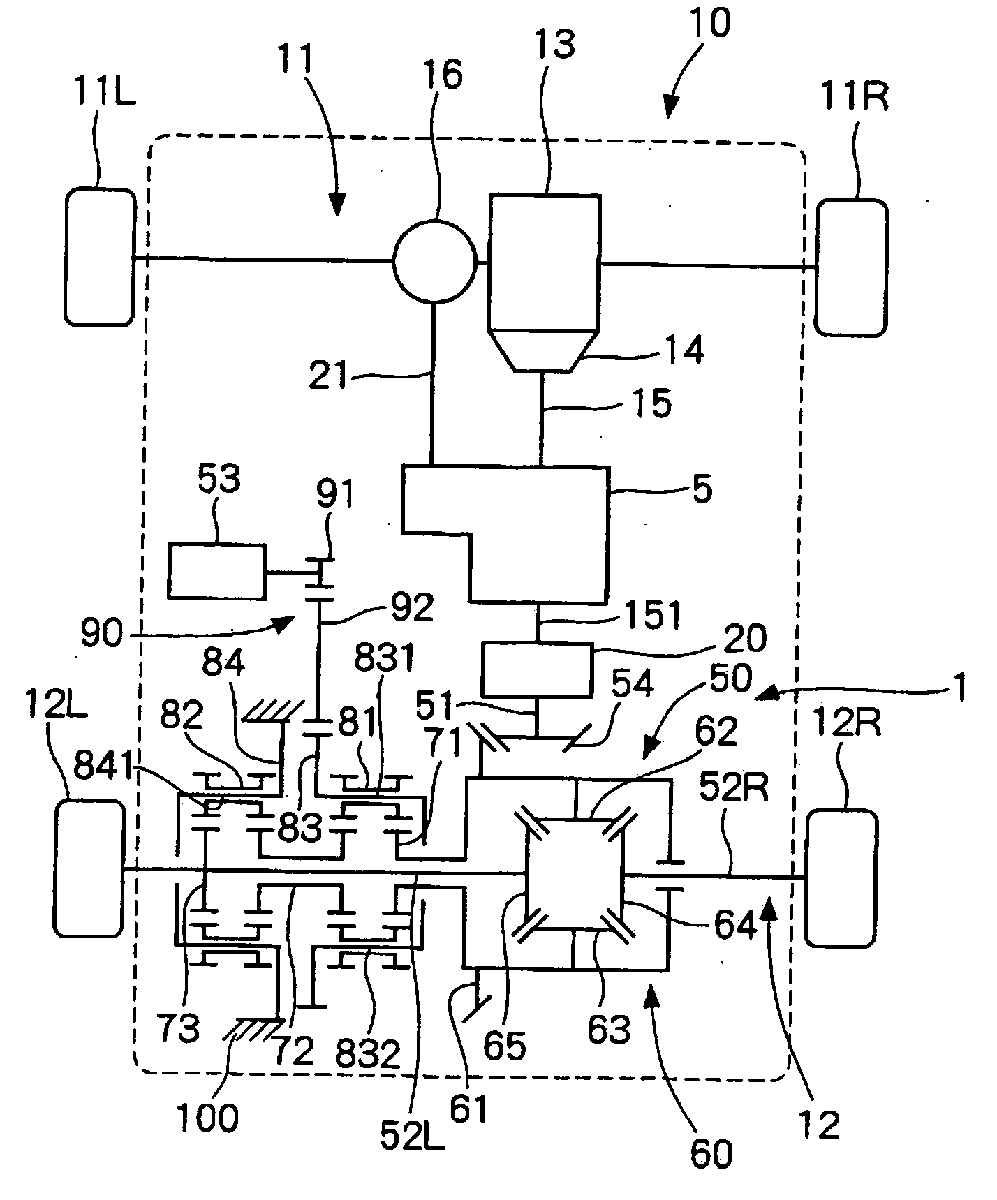
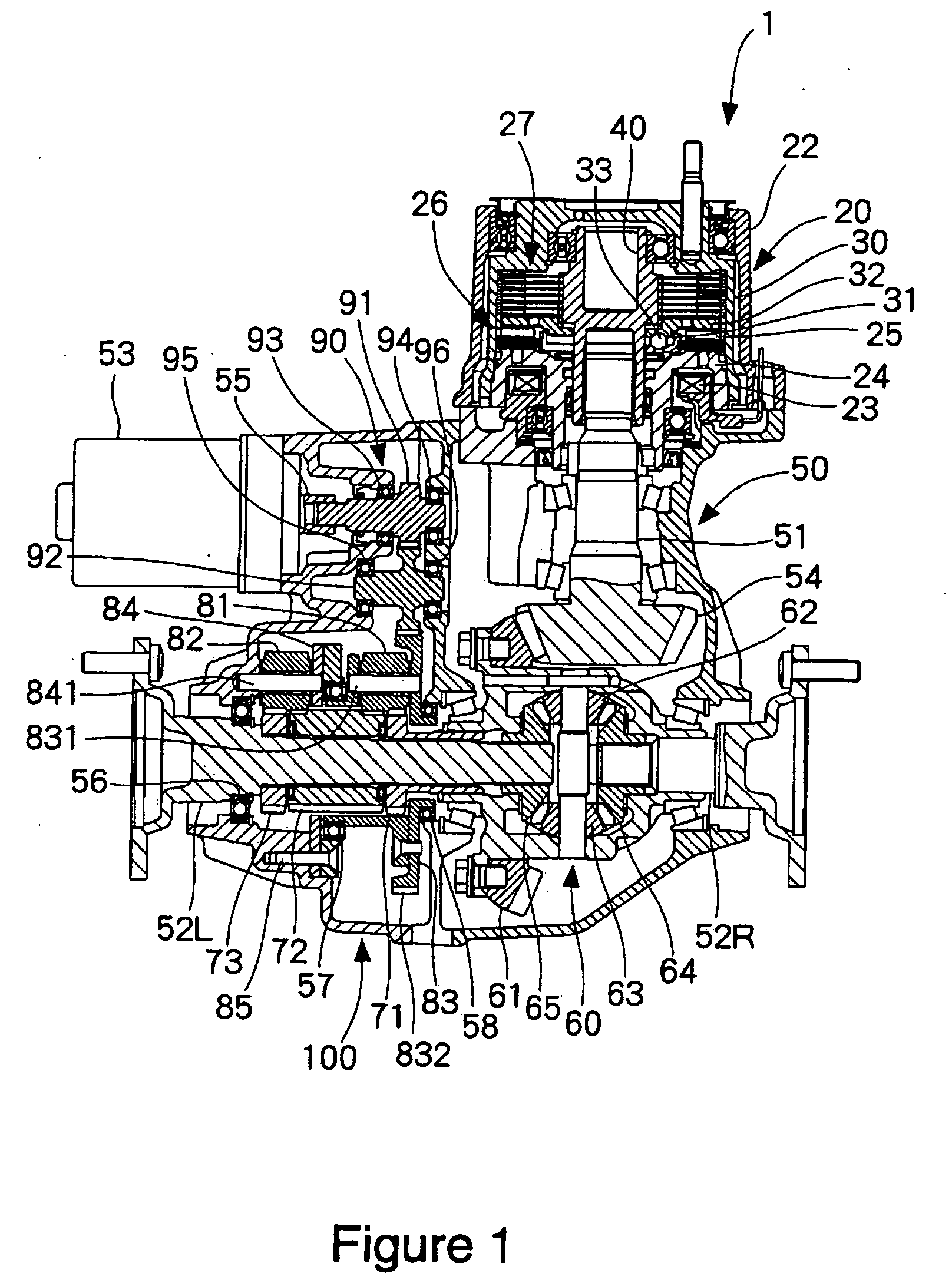
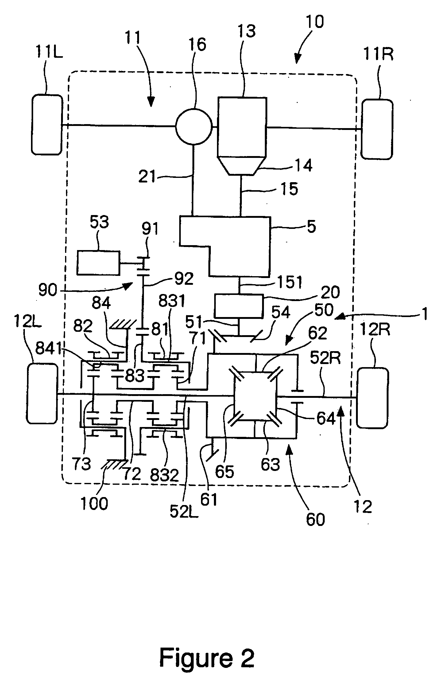
[0018]FIG. 2 shows a vehicle 10 provided with a differential device 50 according to an embodiment of the present invention. The vehicle 10 shown in FIG. 2 is a four-wheel drive vehicle where torque is applied to both of a set of front wheels 11 and a set of rear wheels 12. The vehicle 10 includes an internal combustion engine (hereinafter, referred to as engine) 13 serving as a first power source, a transmission 14, a transfer 5, a drive power transmission device 20 and the differential device 50. As shown in FIG. 1, the differential device 50 and the drive power transmission device 20 are configured as an integrated drive power transmission unit 1. In the vehicle 10 of this embodiment shown in FIG. 2, the front wheels 11 consist of a front left wheel 11L and a front right wheel 11R, while the rear wheels 12 consist of a rear left wheel 12L and a rear right wheel 12R.

[0019] For example, a gasoline engine or a diesel engine can be adopted as the engine 13. An electric motor may be a...

embodiment 2

[0045] A differential device 50′ according to another embodiment of the present invention is shown in FIGS. 5 and 6. Substantially same portions as the former embodiment are indicated by the same reference number as that of the former embodiment, and explanations for the same portions are omitted.

[0046] As shown in FIGS. 5 and 6, this embodiment is different from the former embodiment in an arrangement of a motor 53′. Configuration of the other parts is same as the former embodiment. The motor 53′ is arranged between the differential device 50′ and the drive power transmission device 20. The differential device 50′ and the drive power transmission device 20 configure an integrated drive power transmission unit 2. The drive power transmission unit 20 includes the casing 100 corresponding to a first housing which houses the differential device 50′ and the cover 22 corresponding to a second housing which houses the drive power transmission device 20. The casing 100 is provided with a ...


PUM


Abstract

The number of the teeth of a second sun gear is slightly different from that of a first sun gear. A first planetary gears mesh with both the first sun gear and the second sun gear. A first carrier supports the first planetary. The number of the teeth of a third sun gear is same as that of the first sun gear. The second planetary gears mesh with both the second sun gear and the third sun gear. The second carrier supports the second planetary gears with preventing the same from revolving. The second power source generates a torque for rotating the first carrier.

Description

INCORPORATION BY REFERENCE [0001] This application based on and claims priority under 35 U.S.C. §119 with respect to Japanese Patent Application No. 2004-298577 filed on Oct. 13, 2004. The contents of that application are incorporated herein by reference. BACKGROUND OF THE INVENTION [0002] 1. Field of the Invention [0003] This invention relates to a differential device for producing difference between rotating numbers of two output elements, and to a drive power transmission unit using the same. [0004] 2. Description of the Related Art [0005] As a conventional differential device for producing difference between rotating numbers of the two output elements, a device employing a planetary gear mechanism has been known in public as described in, for example, Japanese Patent No. 3247484. In the differential device disclosed in the Patent, torque of a electric motor is transmitted to two output elements through a planetary gear mechanism, whereby the difference generated between the two ...

Claims


Application Information

Patent Timeline
Patent Type & Authority Applications(United States)
IPC IPC(8): F16H48/06F16H48/08F16H48/20F16H48/30F16H48/36F16H48/38
CPCB60K6/365B60K6/46B60K6/52F16H3/724F16H48/06Y02T10/6217Y02T10/6265F16H2048/364Y02T10/62
Inventor KUSHINO, HIROSHI
Owner JTEKT CORP
Why Eureka
Try Eureka