Expandable mandrel for use in friction stir welding

Inactive Publication Date: 2006-04-20
MAZAK CORP
View PDF44 Cites 26 Cited by
  • Summary
  • Abstract
  • Description
  • Claims
  • Application Information

AI Technical Summary

Benefits of technology

[0024] It is another object to provide an expandable mandrel that is lighter in weight and therefore easier to use than those used in the prior art.
[0025] It is another objec

Problems solved by technology

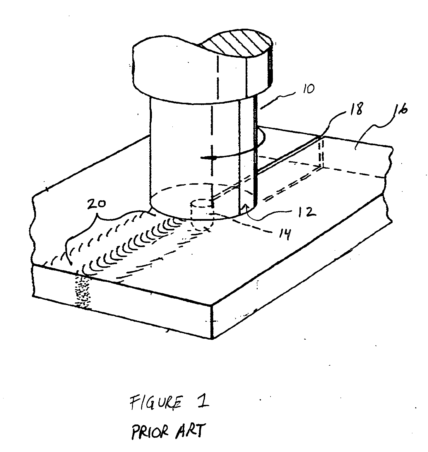
Force is exerted to urge the spindle and the workpieces together and frictional heating caused by the interaction between the spindle and the workpieces results in plasticization of the material on either side of the joint.
Some of these materials are non-fusion weldable, or just difficult to weld at all.
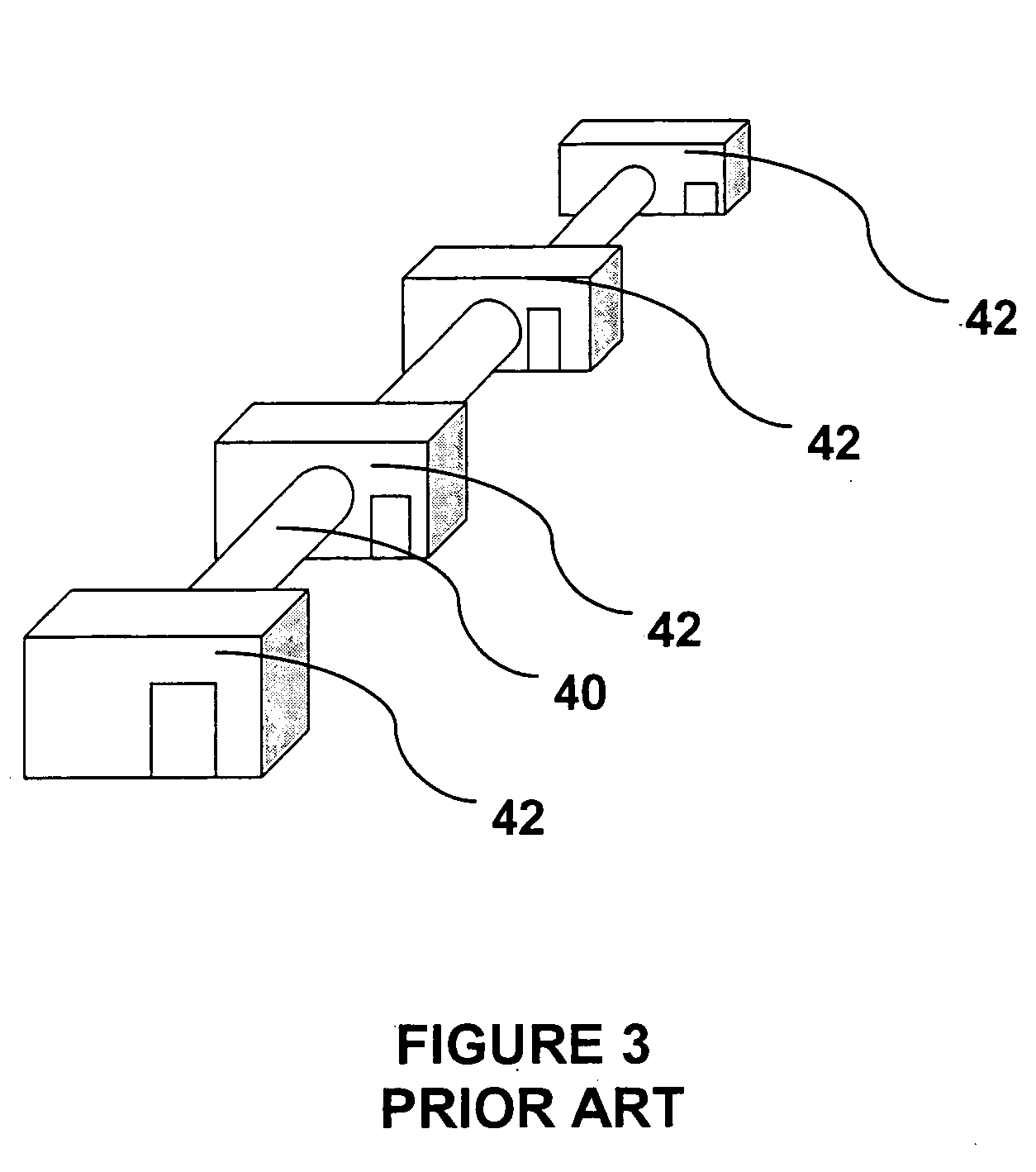
Joining pipe line is extremely costly because of the manpower and equipment needed to weld and move needed components. FIG. 3 shows the manpower and equipment needed to fusion weld a typical pipeline.
The difficulty with AHSS lies in the conventional fusion welding methods being used.
These defects are accepted because they cannot be eliminated even

Method used


Image

  • Expandable mandrel for use in friction stir welding
  • Expandable mandrel for use in friction stir welding
  • Expandable mandrel for use in friction stir welding

Examples


Example

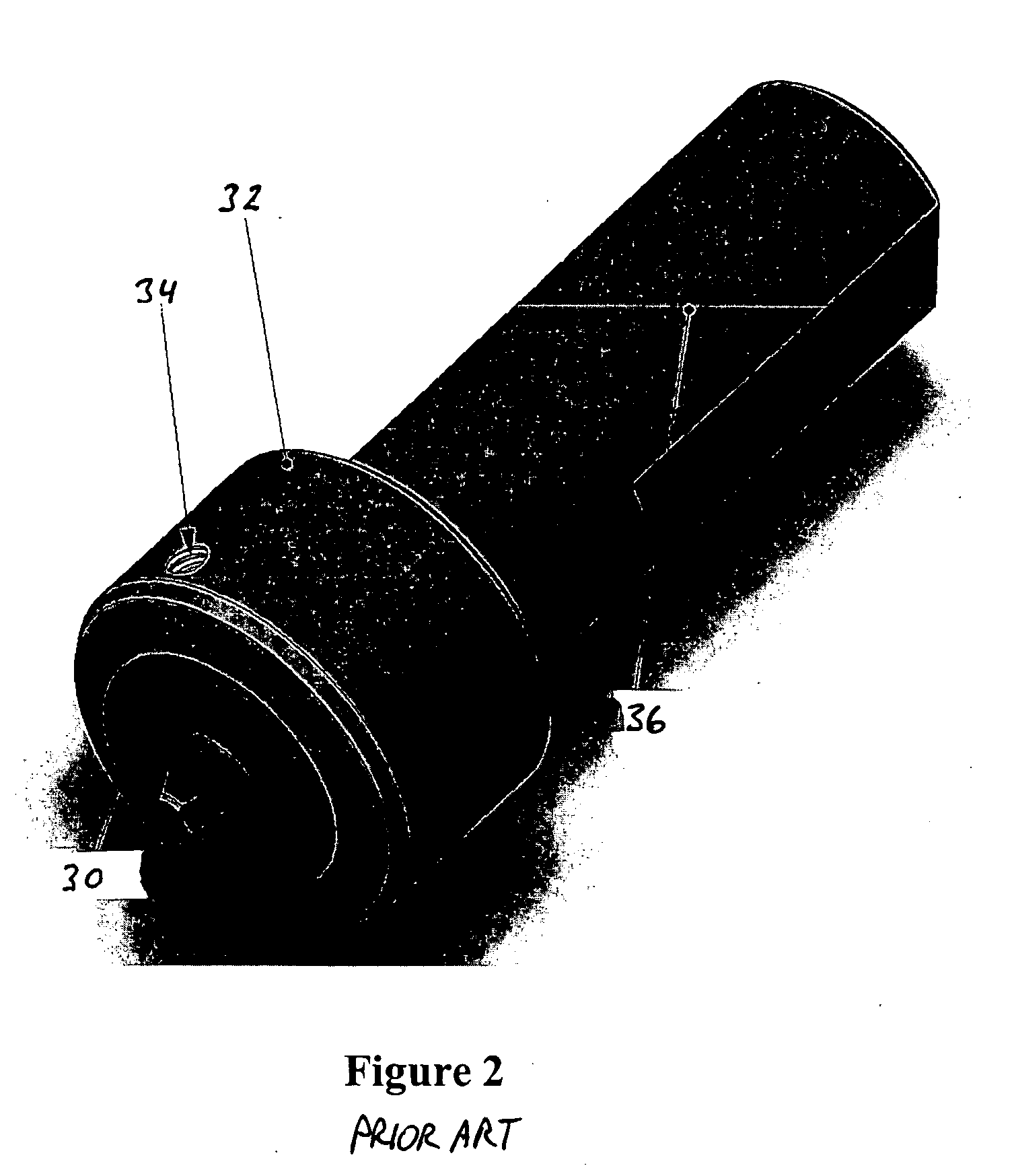
[0041]FIG. 6 shows a first embodiment of a mandrel shell 72 that forms an outer shell of the mandrel or “pipe pig”70 of the present invention. The mandrel shell 72 is a hollow cylinder having an opening or gap 74 along the length thereof. The diameter of the mandrel shell 72 is selected so that the mandrel shell will slide inside of the pipe segments (not shown) that are to be welded, when the gap 74 is allowed to close.

[0042]FIG. 6 also illustrates relief cuts 76 that are made on the inside diameter 78 of the mandrel shell 72 so that the mandrel shell can spring and flex at the locations of the relief cuts 76. Once the mandrel shell 72 is machined, lips 80 are welded into place on the inside diameter 78 of the mandrel shell 72 immediately adjacent to the gap 74 as shown in FIG. 7.

[0043] Once the lips 80 have been welded into place, the mandrel shell 72 is further modified so that the gap 74 is naturally in a closed position when there is no external force being applied to the man...


PUM

PropertyMeasurementUnit
Diameteraaaaaaaaaa
Sizeaaaaaaaaaa
Residual stressaaaaaaaaaa

Abstract

A mandrel that provides a counter-force to the pressure exerted on the outside of a pipe or other arcuate surface by a friction stir welding tool, wherein the mandrel is expandable through the use of a wedge, and wherein the mandrel enables multiple friction stir welding heads to simultaneously perform welding on the arcuate surface.

Description

BACKGROUND OF THE INVENTION [0001] 1. Field of the Invention [0002] This invention relates generally to friction stir welding. More specifically, the present invention addresses improvements in the ability to perform friction stir welding of pipe or other arcuate objects, wherein a mandrel is needed to provide a counter-balancing force against the inside of the arcuate surface being welded, to thereby prevent a friction stir welding tool in contact with the outside of the arcuate surface from damaging the workpiece being welded. [0003] 2. Description of Related Art [0004] Friction stir welding (hereinafter “FSW”) is a technology that has been developed for welding metals and metal alloys. The FSW process often involves engaging the material of two adjoining workpieces on either side of a joint by a rotating stir pin or spindle. Force is exerted to urge the spindle and the workpieces together and frictional heating caused by the interaction between the spindle and the workpieces resu...

Claims


Application Information

Patent Timeline
IPC IPC(8): B23K20/12
CPCB23K20/126B23K37/0426B23K37/0531B23K2201/06B23K2101/06B23K20/12
Inventor PACKER, SCOTT M.BABB, JONATHAN A.STEEL, RUSSELL J.RUSSELL, MONTE
Owner MAZAK CORP
Why Eureka
Try Eureka