Actuator for operating a valve in process automation

Inactive Publication Date: 2006-04-20
AUMA RIESTER GMBH & CO KG
View PDF8 Cites 30 Cited by
  • Summary
  • Abstract
  • Description
  • Claims
  • Application Information

AI Technical Summary

Benefits of technology

[0022] In principle, when the application permits, the actuator can be connected directly to the current supply just long enough to adjust the valve to the desired position. However, it is especially advantageous in connection with the actuator o

Problems solved by technology

Due to the long-needed transmission for reducing the rotational speed of the electric motor, for example, from e.g. 3000 RPM to a low rotational speed, the known actuators h

Method used


Image

  • Actuator for operating a valve in process automation
  • Actuator for operating a valve in process automation
  • Actuator for operating a valve in process automation

Examples


Embodiment Construction

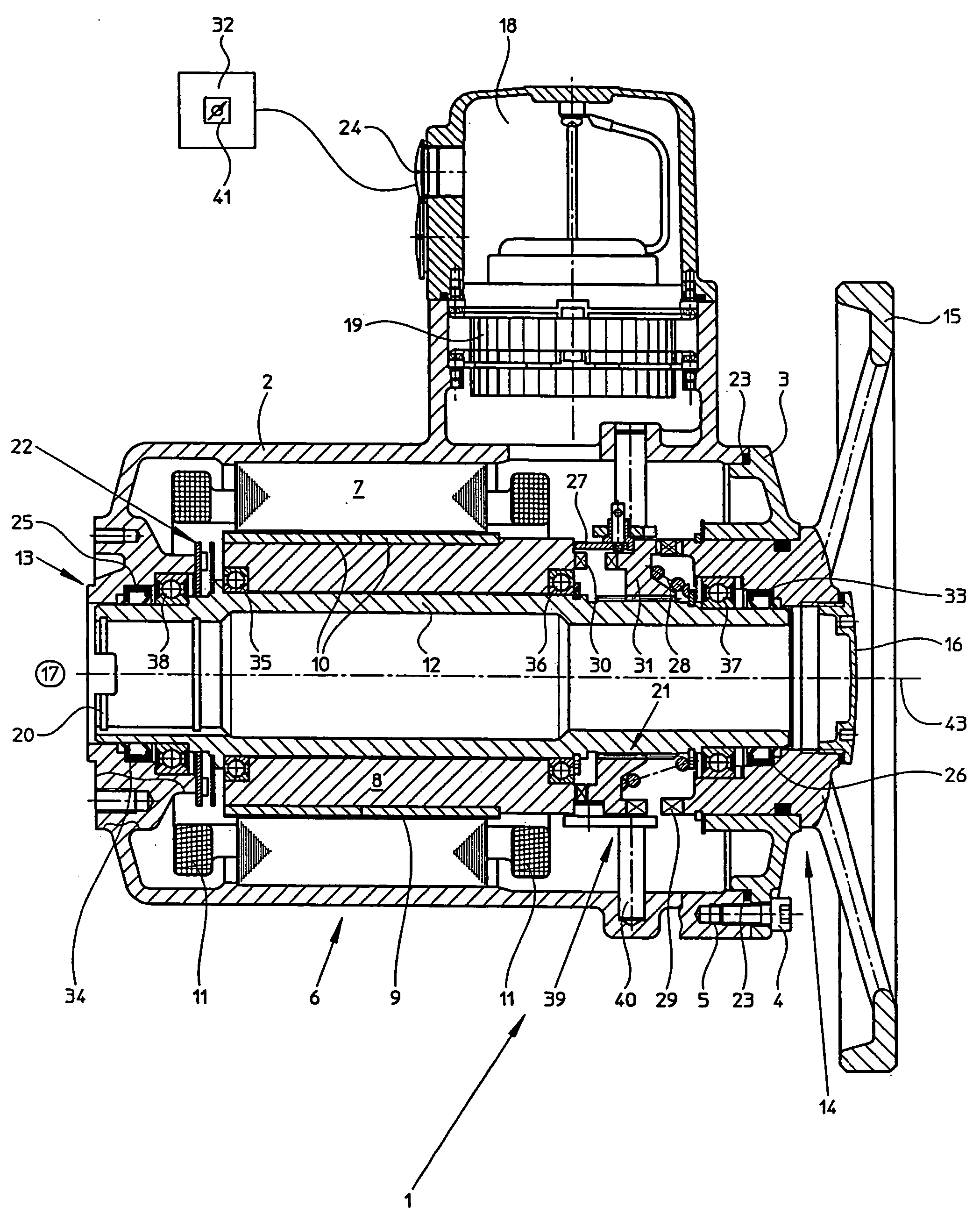
[0032]FIG. 1 shows a longitudinal section through a first form of embodiment of the actuator 1 of the invention. The actuator 1 is distinguished by a very compact form of construction. By omitting the reduction transmission, an increased stiffness of the actuator 1 is achieved. As a consequence, the actuator 1 of the invention is suited for highly accurate positioning tasks; additionally, it tolerates high accelerations, which results in a shortened cycle time.

[0033] Essential components of the actuator 1 of the invention are the electric motor 6 and the separately—thus independently of the electric motor 6—operable adjustment wheel 15. The electric motor 6 includes an output shaft 12, a rotor 8 and a stator 7. In the left, first end-region 13 of the output shaft 12, a valve connection 20 is provided for the coupling of the actuator 1 to a valve 17 (shown symbolically in FIG. 1). Valve 17 is preferably a control element, e.g. a globe-, gate-, throttle- or butterfly-valve. The valve...


PUM


Abstract

A actuator for operating a valve in process automation. The actuator includes a separately operable, adjustment wheel and an electric motor having at least a stator and a rotor. The stator and rotor are associated with predetermined regions of an output shaft. A valve connection is provided in a first end region of the output shaft for coupling the actuator to the valve. The adjustment wheel is arranged in a second end region of the output shaft.

Description

FIELD OF THE INVENTION [0001] The invention relates to an actuator for operating a valve in process automation. The valve is, preferably, a control element, e.g. a globe-, gate-, throttle- or butterfly-valve. Depending on the control element, the operating, or adjusting, process involves a rotary, translatory or pivoting motion. Electric actuators for valves must, for such purposes, be designed to be able to transmit high torques (30-500,000 Nm) at low rotational speeds (4-180 RPM), with it being necessary that the transmitted torque remain very constant over small angles of rotation. BACKGROUND OF THE INVENTION [0002] Electric actuators for regulating and / or controlling valves have become an integral part of process automation. In the case of known actuators, torque transfer between electric motor and valve occurs via a reduction transmission, which, depending on application, is embodied in many different ways. The reduction transmission is necessary, in order to convert the high r...

Claims


Application Information

Patent Timeline
IPC IPC(8): F16K31/02
CPCF16K31/05H02K7/14
Inventor RIESTER, WERNERNEWERLA, HENRIK
Owner AUMA RIESTER GMBH & CO KG
Why Eureka
Try Eureka