Autonomous operation control system

Inactive Publication Date: 2006-04-20
INC ADMINISTRATIVE AGENCY NAT AGRI & BIO ORIENTED RES ORG
View PDF2 Cites 14 Cited by
  • Summary
  • Abstract
  • Description
  • Claims
  • Application Information

AI Technical Summary

Benefits of technology

[0016] According to the autonomous operation control system according to the above aspect, images photographed by the shooting unit are classified according to recording time and stored in the storage device or the external storage device provided at a different location, and a specific person is allowed to view the image data through an authentication function.
[0017] The autonomous operation controller of the autonomous operation control system according to the above aspect transmits a signal based on the image from the monitoring apparatus and information from a sensor, and gives an instruction to a subject based on the signal.
[0018] The autonomous operation controller of the autonomous operation control system according to the above aspect further includes a control function of controlling the photographic subject by the shooting unit to dynamically determine a photographic direction using the image information acquired from a plurality of locations; and a simultaneous photographing function of photographing the photographic subject from the multiple directions simultaneously.
[0019]

Problems solved by technology

However, if a monitoring target (the photographic subject) is, for example, a weather observation apparatus, the camera is disadvantageously insufficient in the number of elements that the camera can measure and in measurement accuracy.
With a control method (photographing method) based on the conventional autonomous operation control system, it is difficult to appropriately grasp the photographic subject and, therefore, disadvantageously difficult to realize automation.
In addition, if the operator or the like is responsible for all operations relating to photographing and the number of photographic subjects and the number of locations at which the photographic cameras are disposed increase, a heavy burden is disadvantageously cast on the operator.
This results in a disadvantageous and considerable increase in a cost of the monitoring apparatus.
In addition, the more complic

Method used


Image

  • Autonomous operation control system
  • Autonomous operation control system
  • Autonomous operation control system

Examples


first embodiment

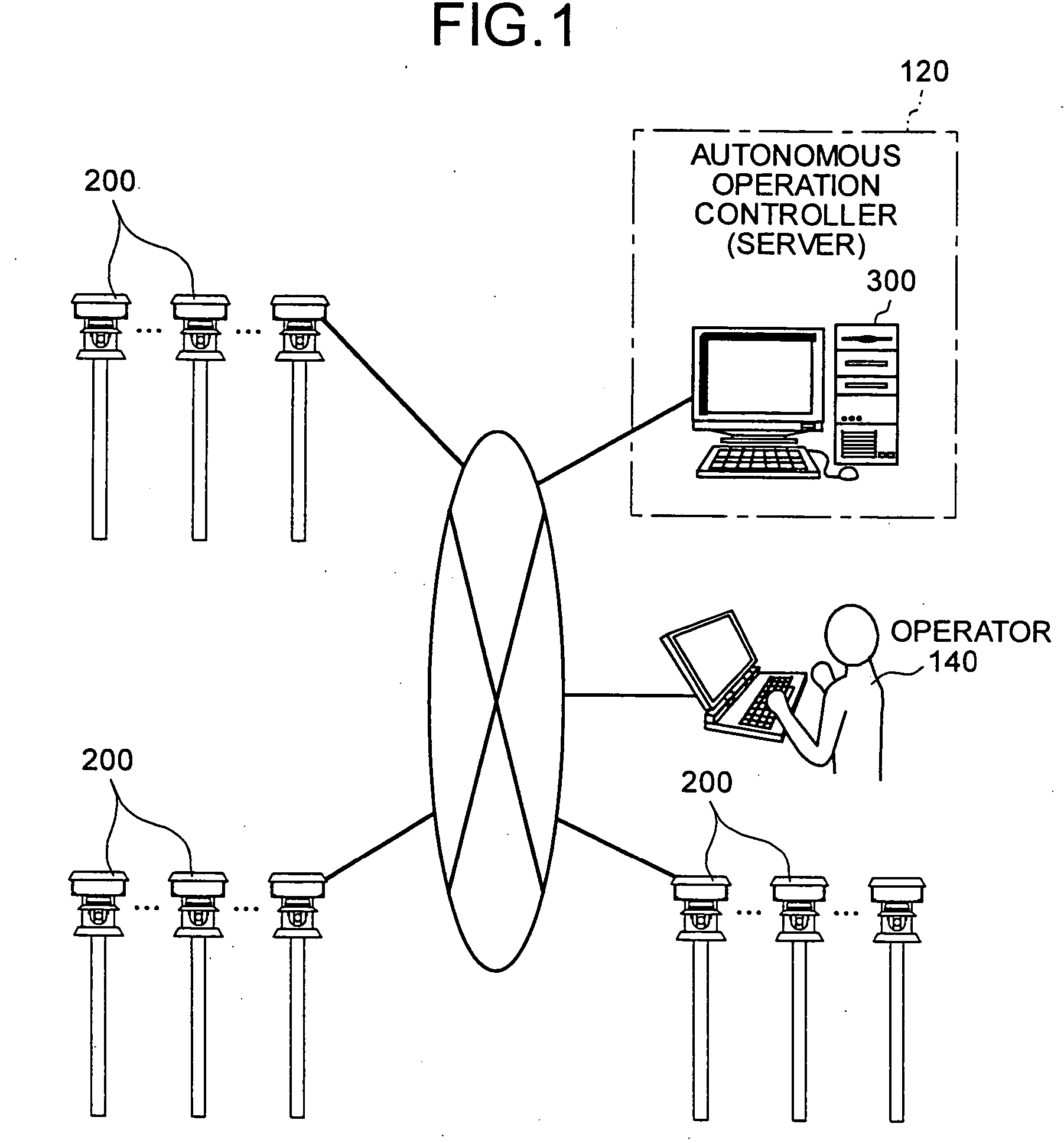
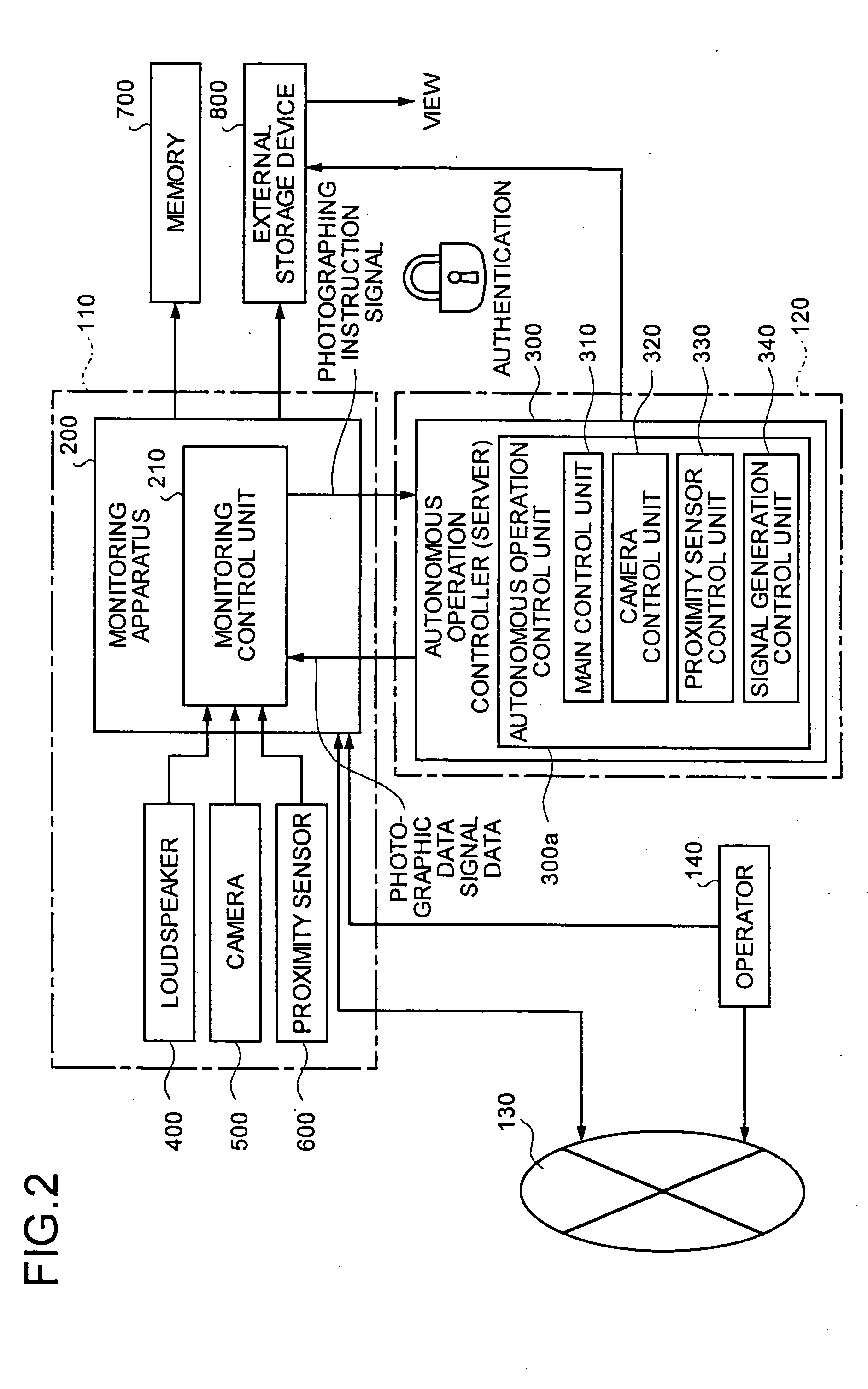
[0024] As shown in FIG. 1, the autonomous operation control system is composed by a plurality of monitoring apparatuses 200 disposed at a first remote location 110 (FIG. 2) and an autonomous operation controller 300 disposed at a second remote location 120. The monitoring apparatuses 200, a terminal device operated by an operator 140, and the autonomous controller 300 are communicably connected to one another by the Internet 130 through either wire or wireless.

[0025] Namely, the autonomous operation control system according to the present invention is featured as follows. The monitoring apparatuses 200 are provided at the first remote location 110. The autonomous operation controller (agent server) 300 is provided, as a server, at the second remote location 120. This autonomous operation controller 300 controls a control program (an agent program) for managing and operating an image measuring unit to operate to thereby allow the agent to perform photographing. In this embodiment, b...

second embodiment

[0034] An autonomous operation control system according to a second embodiment of the present invention will be explained. Specifically, as shown in FIG. 4, the autonomous operation control system according to this second embodiment is featured as follows. A communication network for all the monitoring apparatuses 300 is constituted by connecting a plurality of monitoring apparatuses 300 to one another over a wireless LAN and setting the respective monitoring apparatuses 300 as relay points. According to the second embodiment, communications of the monitoring apparatuses 300 can be controlled in a wide range, and an efficient autonomous operation system can be constituted.

[0035] Furthermore, if many monitoring apparatuses 300 are disposed, the relay points can be dynamically changed. Due to this, even if a communication on a line is shut off halfway by an accident, a destructive activity, or the like, the autonomous operation controller dynamically changes the path using the normal...

third embodiment

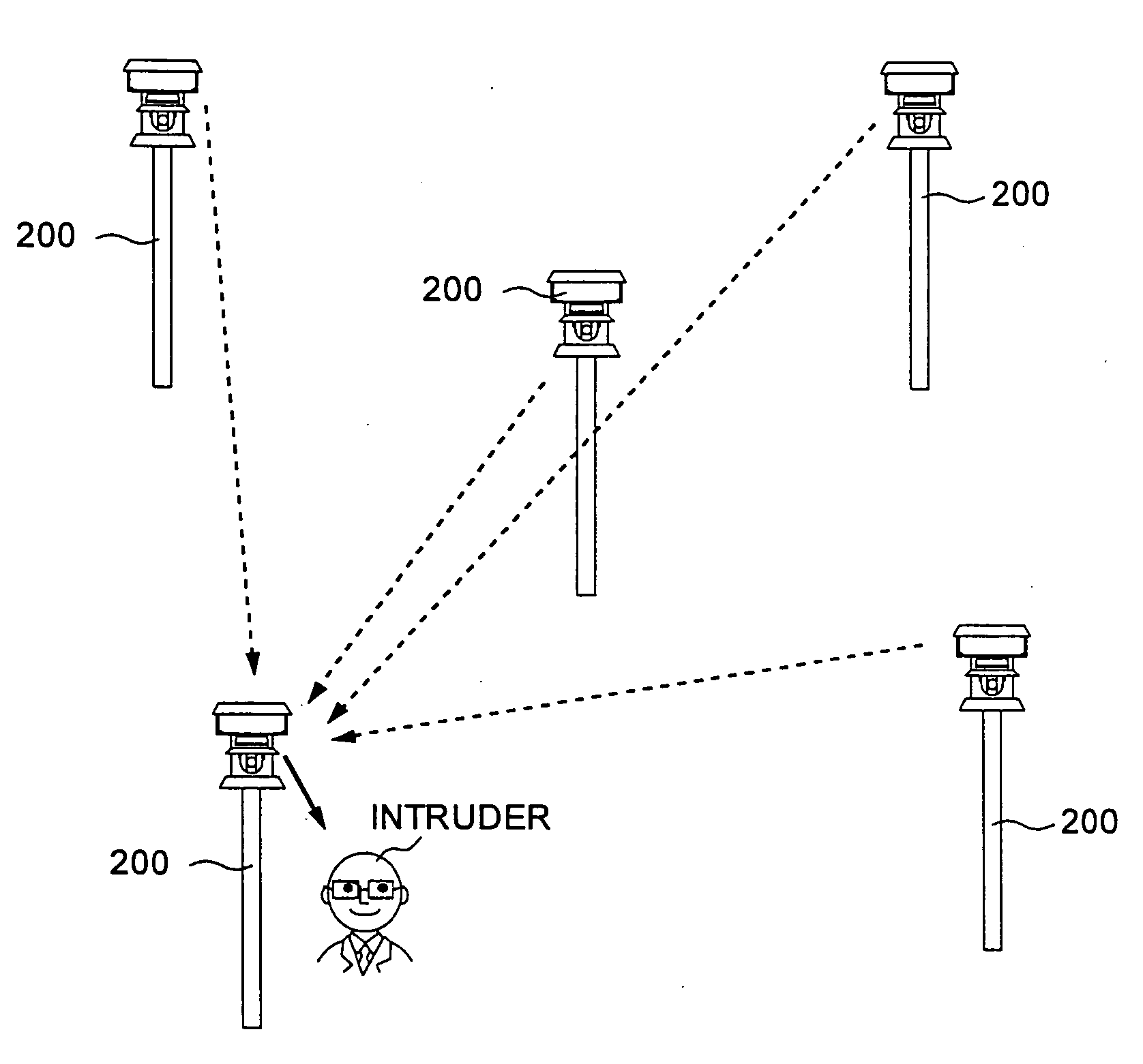
[0036] An autonomous operation control system according to a third embodiment of the present invention will be explained. According to the third embodiment, the camera 500 provided in each monitoring apparatus 200 has a zoom function of macro-photographing a photographic subject. Namely, the autonomous operation control system according to the present invention can be also applied to crime prevention and alarming system for preventing crimes or the like. FIG. 5 is an overall explanatory view for explaining an example in which the autonomous operation control system according to the present invention is used as the crime prevention and alarming system. Namely, FIG. 5 is an example of disposing five monitoring apparatuses 200 at respective locations intended for prevention of crimes. Each monitoring apparatus 200 includes the proximity sensor 600 and the camera 500 having the zoom function. In this example, a site on which the monitoring apparatus 200 disposed at the center, among the...


PUM


Abstract

A monitoring apparatus including a loudspeaker, a photographic camera that photographs image information on a photographic subject, a proximity sensor, and a monitoring control unit is disposed at a first remote location. An autonomous operation controller including an autonomous operation control unit is disposed at a second remote location remote from the first remote location. Under remote control of this autonomous remote controller, the monitoring apparatus performs photographing of the image information on the photographic subject and acquires the image information.

Description

TECHNICAL FIELD [0001] The present invention relates to an autonomous operation control system including an autonomous operation controller (a monitoring apparatus) that monitors a photographic subject at a remote location or the like, and more particularly, to an autonomous operation control system that can operate and acquire shooting of the photographic subject, such as image information, from other remote location. BACKGROUND ART [0002] A conventional method of acquiring image information of a remote location is to setup a camera on the spot and transfer the image information taken via a wired or a wireless scheme. The method of transferring the image information taken via the wired or the wireless scheme to acquire the image information of the remote location is referred to as “a remote technique”, “a monitoring technique”, “an Internet technique”, or “a long-time monitoring technique” (hereafter, “autonomous operation control system”, generically in this specification). [0003]...

Claims


Application Information

Patent Timeline
IPC IPC(8): H04N7/18G06Q50/00G06Q50/02G08B13/196G08B25/00G08B25/01G08B25/04
CPCG08B13/19645G08B13/19656G08B13/19695
Inventor HIRAFUJI, MASAYUKIFUKATSU, TOKIHIRO
Owner INC ADMINISTRATIVE AGENCY NAT AGRI & BIO ORIENTED RES ORG
Why Eureka
Try Eureka