Reverse angled threadform with anti-splay clearance

a reverse angled and clearance technology, applied in the direction of screws, osteosynthesis devices, applications, etc., can solve the problems of implant design, implant failure, and surgeons installing implants, and achieve the effect of improving the threadform, reducing the likelihood of failure of the implant and the closure system during use, and advantageous application

Inactive Publication Date: 2006-04-20
JACKSON
View PDF44 Cites 78 Cited by
  • Summary
  • Abstract
  • Description
  • Claims
  • Application Information

AI Technical Summary

Benefits of technology

[0021] Therefore, objects of the present invention include: providing an improved threadform; providing such an improved threadform which has particularly advantageous application on an open headed lightweight and low profile medical implant; providing a threadform for such an implant which has a pair of spaced arms and the closure closes between the arms to clamp structure such as a spinal fixation rod therein; providing such a threadform which is a reverse angled threadform that resists tendencies of the arms to splay or separate during insertion of the closure, to thereby reduce the likelihood of failure of the implant and closure system during use; providing such a threadform which enables the closure to be installed at comparatively high torques to thereby secure the closure in the receiver channel and in certain embodiments to also lock a rod member in the open head of the implant where the closure engages and is urged against the rod by rotation in a receiver channel of the remainder of the implant; providing such a thread or threadform including clearance between elements of the threads to avoid galling and / or distortion of the threads when a closure is applied at high levels of torque within the head of the implant; providing a configuration of such a threadform with angular peaks in which the anti-splay clearance is implemented as space between stab flanks of the threads; providing a configuration of such a threadform with cylindrical crest and root surfaces in which the anti-splay clearance is implemented as space between the crest and root surfaces of the threads; providing such a threadform in which the threads of inner and outer members are proportioned and configured in such a manner as to control the relative levels of stress which are applied to the inner and outer threads when the threaded joint is strongly torqued; providing such a threadform in which the load flanks are substantially parallel; providing such a threadform in which the load flanks diverge in a radially outward direction; providing such a threadform in which the load flanks converge in a radially outward direction; providing such a threadform which can be formed relatively economically using appropriate metal forming technologies; and providing reverse angled threadforms with anti-splay clearance, particularly for implant and bone fixation hardware, which are economical to manufacture, which are secure and efficient in use, and which are particularly well adapted for their intended usage.
[0022] Other objects and advantages of this invention will become apparent from the following description taken in conjunction with the accompanying drawings wherein are set forth, by way of illustration and example, certain embodiments of this invention.
[0023] The drawings constitute a part of this specification and include exemplary embodiments of the present invention and illustrate various objects and features thereof.

Problems solved by technology

Medical implants present a number of problems to both surgeons installing implants and to engineers designing them.
These are normally conflicting goals, and often difficult to resolve.
One type of implant presents special problems.
While the open headed devices are often necessary and preferred for usage, there is a significant problem associated with them.
However, such threaded closures have encountered problems in that they produce radially outward forces that lead to splaying of the arms or at least do not prevent splaying that in turn loosens the implant.
In either case, the unfortunate effect was to substantially increase the weight, size, and the profile of the implant.
However, it is often difficult to capture a portion of a curved rod in a short bone screw head to clamp it within the bone screw.

Method used


Image

  • Reverse angled threadform with anti-splay clearance
  • Reverse angled threadform with anti-splay clearance
  • Reverse angled threadform with anti-splay clearance

Examples


Embodiment Construction

[0038] As required, detailed embodiments of the present invention are disclosed herein; however, it is to be understood that the disclosed embodiments are merely exemplary of the invention, which may be embodied in various forms. Therefore, specific structural and functional details disclosed herein are not to be interpreted as limiting, but merely as a basis for the claims and as a representative basis for teaching one skilled in the art to variously employ the present invention in virtually any appropriately detailed structure.

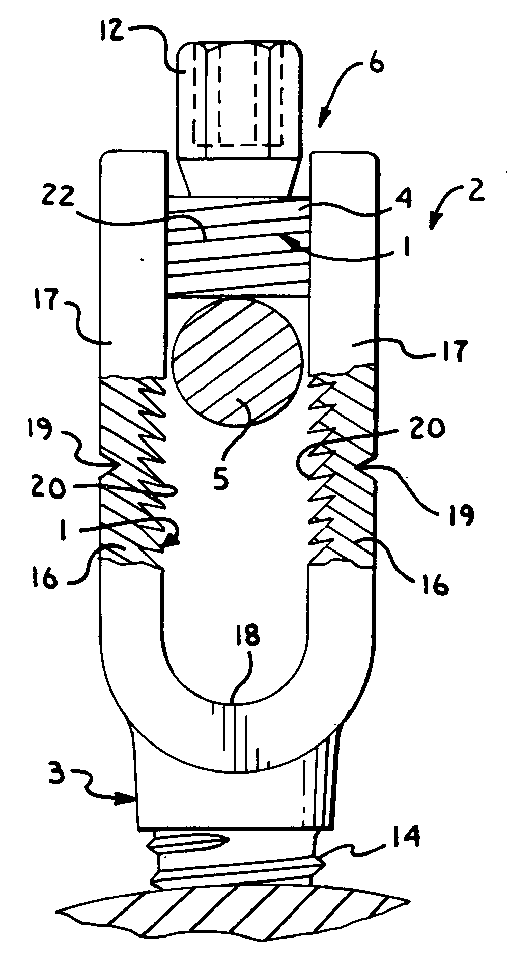
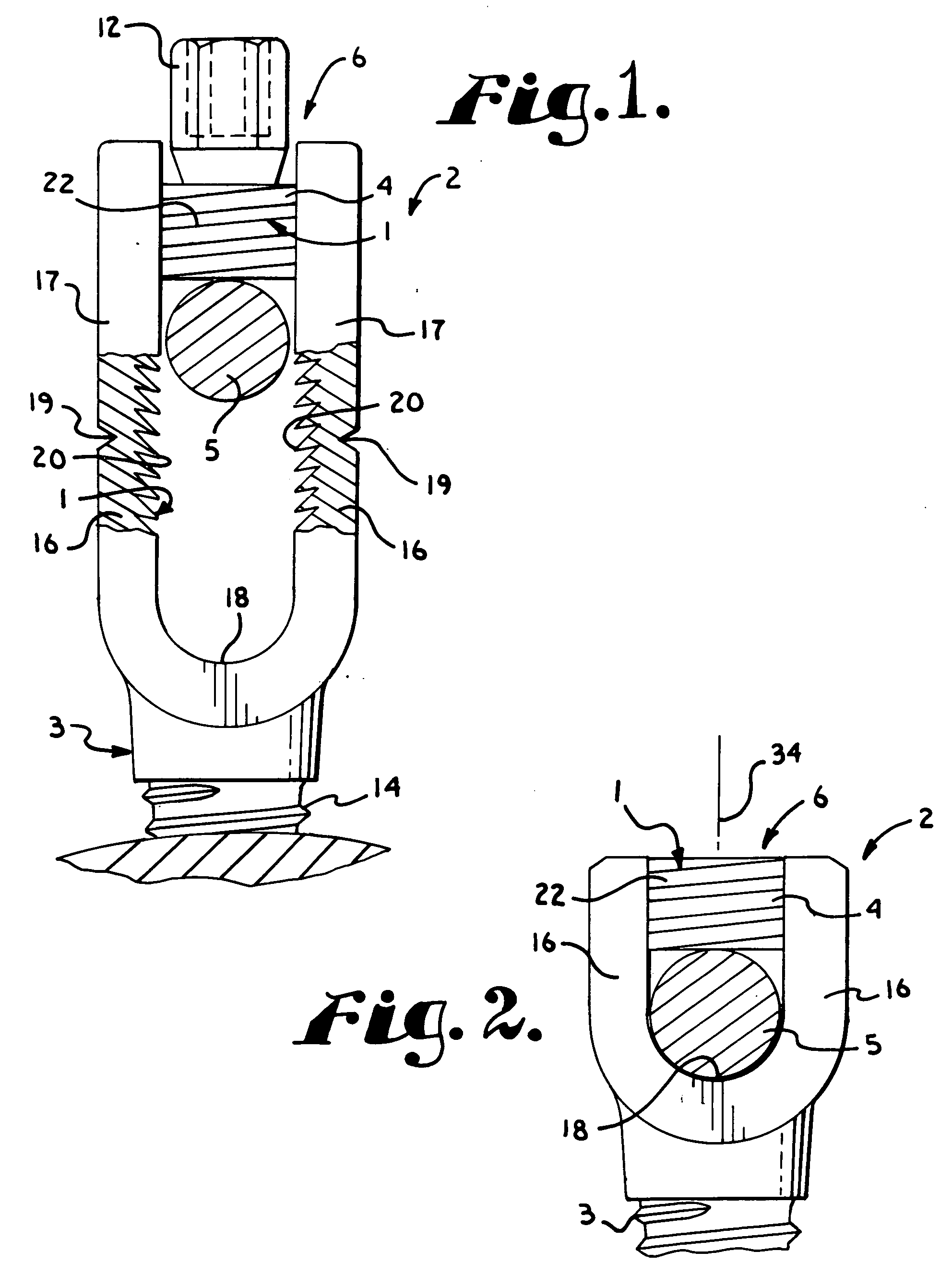
[0039] Referring to the drawings in more detail, the reference numeral 1 generally designates a reverse angled threadform with anti-splay clearance which embodies the present invention. The threadform 1 is incorporated in a spinal fixation anchor 2 formed by an open headed bone screw 3 and a closure 4 that is received in the bone screw 3 to clamp and thereby anchor a spinal fixation rod 5. Although the threadform 1 is foreseen to have wider and more diverse...


PUM


Abstract

A reverse angled threadform with anti-splay clearance includes inner and outer helical threads, each with respective leading stab flanks and trailing load flanks, the load flanks mutually engaging when an inner member with the inner threads is advanced into an outer member with the outer threads. The inner load flanks form acute angles with a helical axis, while the outer load flanks form obtuse angles with the helical axis. The clearance is formed between the stab flanks of the inner and outer threads. On threadforms with root and crest other than angular peaks, such as cylindrical root and crest surfaces, the anti-splay clearance is also formed between the mutually facing root and crest surfaces of the inner and outer threads. The load flanks may be parallel, outwardly diverging, or outwardly converging.

Description

CROSS-REFERENCE TO RELATED APPLICATION [0001] This is a continuation-in-part of U.S. patent application, Ser. No. 09 / 644,777 for THREADFORM FOR MEDICAL IMPLANT CLOSURE filed Aug. 23, 2000, now U.S. Pat. No. ______ , and a continuation-in-part of U.S. patent application Ser. No. 11 / 246,320 for HELICAL REVERSE ANGLE GUIDE AND ADVANCEMENT STRUCTURE WITH BREAK-OFF EXTENSIONS, filed Oct. 7, 2005, now U.S. Pat. No. ______, which are incorporated herein by reference.BACKGROUND OF THE INVENTION [0002] The present invention relates to improvements in helical guide and advancement structures such as threads and to forming guide and advancement structures in such a manner as to control the relative loading or stressing of the male and female components of such structures. More particularly, the present invention relates to forming reverse angled threads with parallel, diverging, or converging load and stab flanks in such a manner as to control relative loading of male and female components of ...

Claims


Application Information

Patent Timeline
Patent Type & Authority Applications(United States)
IPC IPC(8): F16B25/00
CPCA61B17/7032A61B17/7037A61B17/864A61B2019/307F16B33/02H01R4/36A61B2090/037
Inventor JACKSON, ROGER P.
Owner JACKSON
Why Eureka
Try Eureka