
Dynamically tensioned peristaltic tubing pump

a peristaltic pump and flex life technology, applied in the direction of pump, positive displacement liquid engine, machine/engine, etc., can solve the problems of affecting maintenance costs, relatively short flex life of tubing materials, and suffer from some drawbacks, so as to reduce the adverse effect of compressing the tubing and reduce the cost of operation. , the effect of prolonging the flex life of the tubing

Inactive Publication Date: 2006-04-20
MAZTECH
View PDF35 Cites 21 Cited by
  • Summary
  • Abstract
  • Description
  • Claims
  • Application Information

AI Technical Summary

Benefits of technology

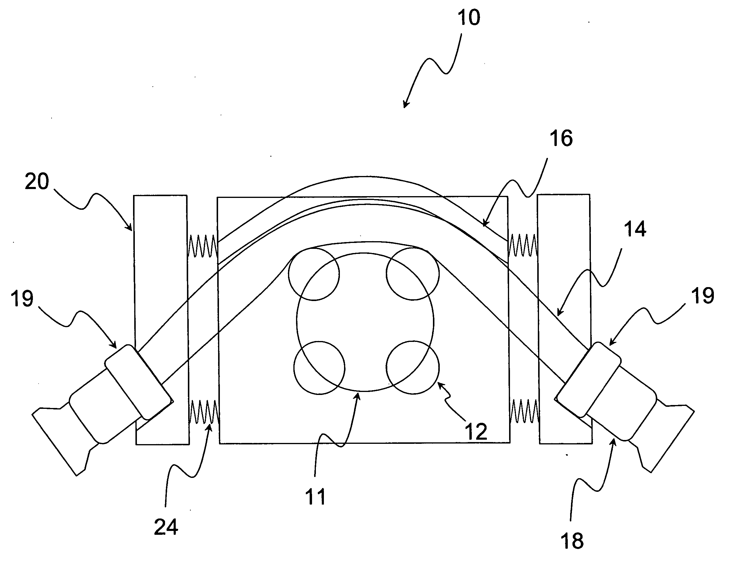
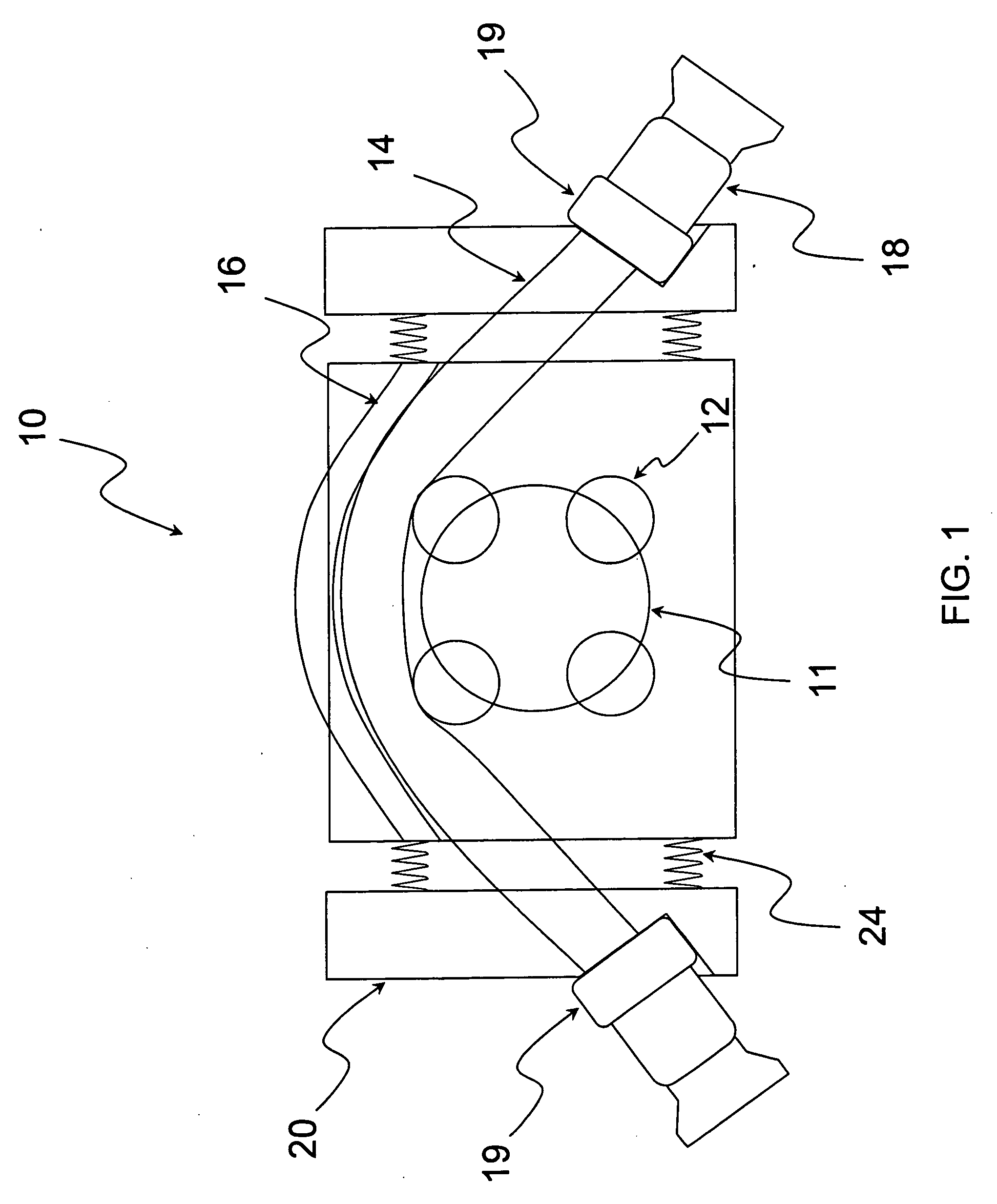
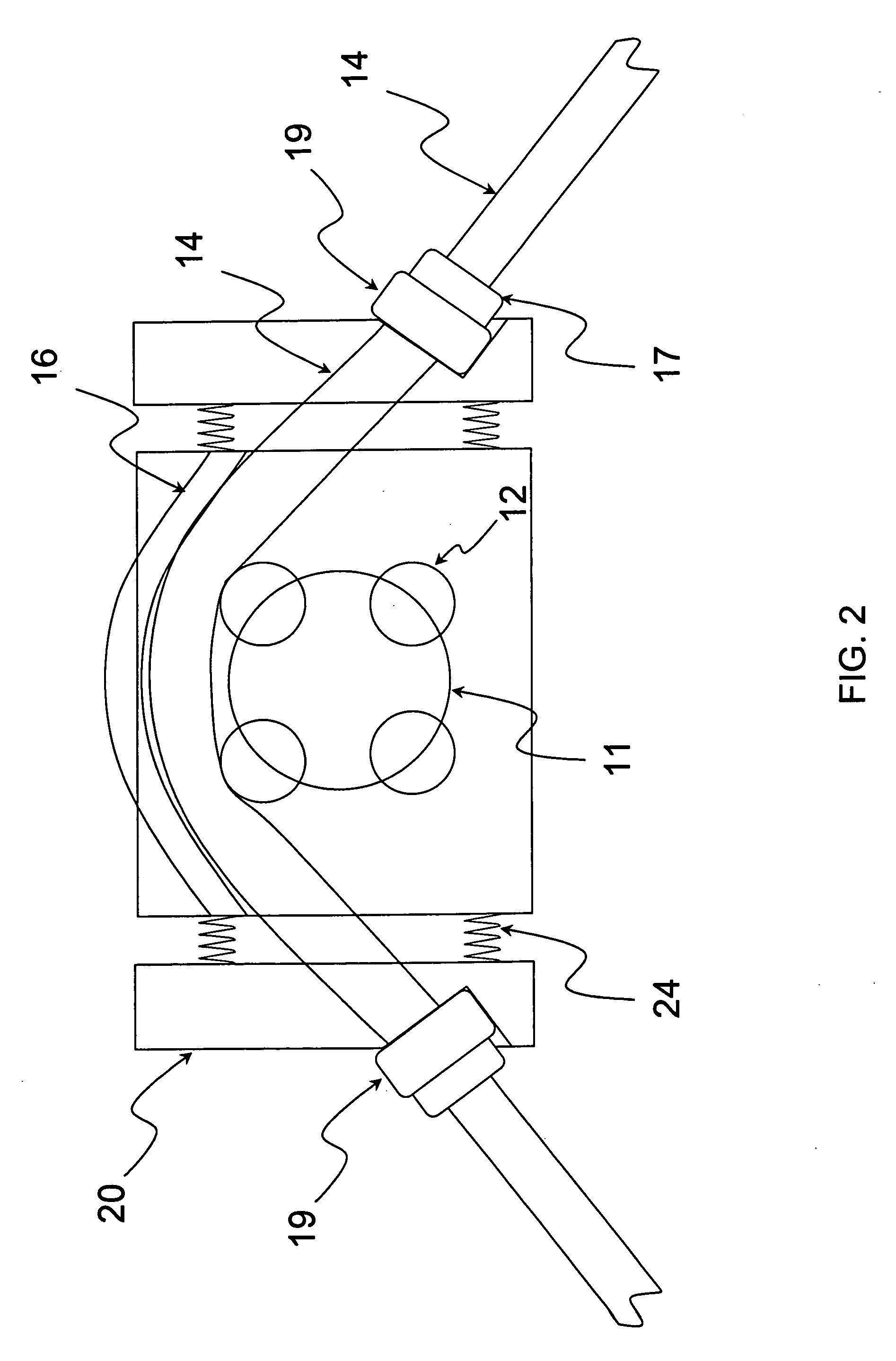
[0013] Another objective of the invention is to provide a compliant material located within a receiving piece attached to the pumphead housing to accept the flanged tubing. This embodiment enables the compliant material to be a permanent part of the pumphead in order to reduce the cost of operation.
[0014] Preferably, the receiving piece is attached to the pumphead housing with shoulder bolts and made compliant via stainless steel springs positioned between the receiving piece and the pumphead. The receiving piece should enable sufficient axial movement of the tubing to reduce the adverse effects of compressing the tubing with the rotor assembly. Preferrably, the springs enable movement up to 10 mm in distance on both the suction and discharge sides of the pump.
[0015] A final objective of the invention is to provide a method of peristaltic pumping whereby the elastomeric tubing communicates with the peristaltic pump in a way that allows for axial movement of the tubing thereby extending the flex life of the tubing.

Problems solved by technology

Although peristaltic pumps have many advantages, they do suffer from some drawbacks.
In particular, if tubing is not properly installed in the pumphead, the tubing can be damaged by the rotor and cause premature failure.
Another disadvantage of peristaltic pumping is the relatively short flex life of the tubing materials.
The flex life often dictates how frequently the tubing needs to be replaced and thus affects the maintenance costs.
This invention, however, overlooks the fact that many tubing materials grow in length upon flexure, and become entangled in the pumhead, thus leading to premature failure.

Method used


Image

  • Dynamically tensioned peristaltic tubing pump
  • Dynamically tensioned peristaltic tubing pump
  • Dynamically tensioned peristaltic tubing pump

Examples


example 1

[0026] A PTFE lined peristaltic pump tube (Part Number SST-16-D), with an inside diameter of 25.4 mm and a wall thickness of 4.8 mm, was obtained from Maztech, Inc. (Rising Sun, Md.) and equipped with male cam and groove fittings. The tubing incorporated two cylindrical polyethylene collars machined to accept the outside diameter of the crimped collar and stepped down to the outside diameter of the tubing so that the collar would apply load to the crimped fitting upon installation into the pumphead, as illustrated in FIG. 1. The polyethylene collars had an outside dimension of 50 mm and communicated with complementary recesses in spring loaded blocks mounted on either side of the pumphead. The plastic blocks were made from two 3″×5″×1″ pieces of filled nylon with a 2 inch diameter recess at an angle of 35 degrees to accept the tubing element. The blocks were mounted onto a Watson Marlow 704S pump. In particular the blocks were retained on the pumphead via stainless steel shoulder bo...

example 2

[0029] A PTFE lined peristaltic pump tube (Part Number SST-16-D) with an inside diameter of 25.4 mm and a wall thickness of 4.8 mm was obtained from Maztech, Inc. (Rising Sun, Md.) with male cam and groove fittings. A stainless steel spring with a spring rate of 2 Kg / mm, a wire diameter of 4.8 mm, and an inside diameter of 32 mm, and a length of 75 mm was placed over the tubing and rested upon a split collar attached to the crimped collar on the end nearest the tubing. Another split collar was attached to the ferrule on the other end of the tubing on the crimped collar. The distance between the spring on one side and the split collar on the other side was controlled to allow for 4 mm of actuation of the spring once mounted into the pumphead housing. Mounting the tube in the pumphead involved using the plastic blocks described in FIG. 3. The blocks were mounted onto a Watson Marlow 704S pump with bolts and the tubing element was snapped into place in the complimentary angled recesses...

example 3

[0031] Another PTFE lined peristaltic pump tube (Part Number SST-12-D), with an inside diameter of 19 mm and a wall thickness of 4.8 mm, was fitted with barb fittings. A piece of silicone tubing with an inside diameter of 28 mm, a length of 15 mm, and a thickness of 5 mm was placed around the outside diameter of the pump tubing on the discharge side of the pump. Split collars were placed around the outside diameter of the pump tubing in order to apply axial load to the unconstrained silicone compliant material and to fit into the complimentary angled recess of the receiving block described in Example 2 The soft silicone ring allowed for axial movement of the pump tubing during operation.

[0032] The Watson Marlow 704 pump was operated at a speed of 250 rpm for 1,080 hours to obtain 65 million compressions until failure. The tubing moved approximately 3 mm in the axial direction during each compression as the pump operated. The tubing remained in the center of the pumphead and did not...


PUM


Abstract

An improved peristaltic pump whereby the elastomeric tubing communicates with the peristaltic pump in a way that allows for axial movement of the tubing thereby extending the flex life of the pump tubing. A tubing element is fitted with a flange that allows tension to be applied to the tubing in a way that changes depending upon the location of the rotor at any given time. The tension can be applied via an elastic material located between the flange and the housing or between the housing and a device that communicates with the flange. The dynamic tension reduces the amount of stress on the tubing material when the rollers first engage the tubing on the suction side of the pump and when they depart the tubing on the discharge side of the pump. The invention is particularly useful for materials that have limited axial flexibility and for those with very large axial flexibility.

Description

[0001] This application claims benefit of provisional application No. 60 / 617,050 filed Oct. 12, 2004.FIELD OF THE INVENTION [0002] The present invention is directed to a dynamically tensioned peristaltic pump. BACKGROUND OF THE INVENTION [0003] Peristaltic pumps are used in numerous applications that require low shear pumping, portability, ability to run dry, ease of cleaning, accurate dosing, etc. These applications can be found in industries ranging from pharmaceutical manufacturing to food processing to water treatment. [0004] The basic principle of peristaltic pumping involves the rotation of a central rotor containing either rollers or fixed shoes against a resilient elastomeric tube surrounding the rotor that is compliant enough to allow for complete collapse from the rotating rollers, and yet elastic enough to recover to a circular cross-section (referred to as restitution) once the rollers pass, thus enabling the next segment of tubing to fill with the process fluid and main...

Claims


Application Information

Patent Timeline
Patent Type & Authority Applications(United States)
IPC IPC(8): F04B43/08F04B43/12F04B45/06
CPCF04B43/0072F04B43/1253
Inventor ZUMBRUM, MICHAEL ALLENCOATES, GEORGE H. III
Owner MAZTECH
Learn More