Ultrasonic doppler measuring apparatus and control method therefor

a doppler and ultrasonic technology, applied in the field of ultrasonic doppler measuring apparatus, can solve the problems of no description about a threshold interval accompanying differences in doppler, and the inability to detect the maximum blood flow velocity vp, and achieve the effect of efficient and accurate generation

Inactive Publication Date: 2006-04-20
TOSHIBA MEDICAL SYST CORP
View PDF5 Cites 25 Cited by
  • Summary
  • Abstract
  • Description
  • Claims
  • Application Information

AI Technical Summary

Benefits of technology

[0015] The present invention has been made in consideration of such problems in the prior art, and has as its object to provide an ultrasonic Doppler measuring apparatus in which when desired trace waveform data is to be generated by setting a threshold for time-serially obtained Doppler spectrum data, a threshold range is set with respect to the Doppler spectrum data on the basis of a spectrum shape model and Doppler sensitivity, and the desired trace waveform data can be efficiently and accurately generated by sequentially updating a predetermined number of thresholds set in the threshold range, and a control method for the apparatus.

Problems solved by technology

According to the method disclosed in U.S. Pat. No. 6,528,321 described above, in some case, however, the maximum blood flow velocity Vp cannot be detected as it is influenced by noise with temporal variations in average signal level and average noise level.
However, there is no description about a method of setting threshold intervals accompanying differences in Doppler sensitivity in the method disclosed in U.S. Pat. No. 6,528,321 or Jpn. Pat. Appln. KOKAI Publication No. 7-303641 described above.

Method used


Image

  • Ultrasonic doppler measuring apparatus and control method therefor
  • Ultrasonic doppler measuring apparatus and control method therefor
  • Ultrasonic doppler measuring apparatus and control method therefor

Examples


first embodiment

(First Embodiment)

(Arrangement of Apparatus)

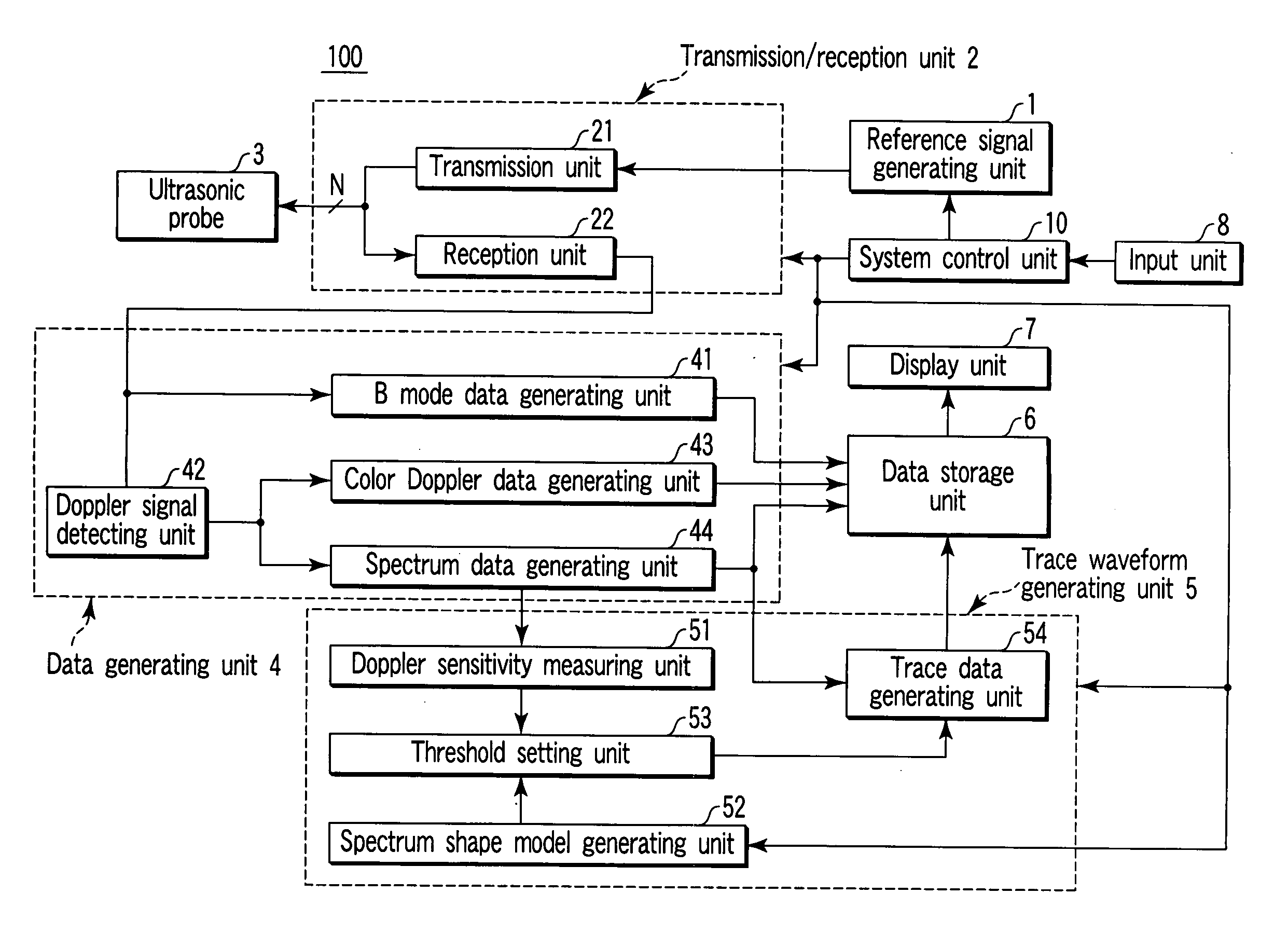
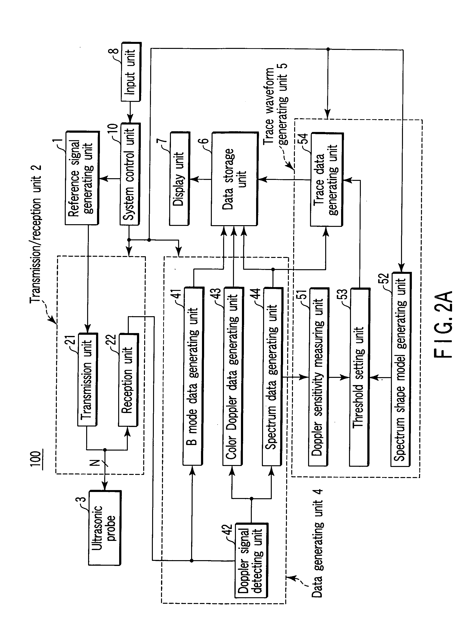
[0036] In the following embodiment of the present invention, a Doppler sensitivity is measured from the average signal level and average noise level of Doppler spectrum data obtained by ultrasonic wave transmission / reception with respect to a predetermined region of an object to be examined. A threshold range in which trace waveform data changes by a predetermined amount in the frequency axis direction is set on the basis of a spectrum shape model generated on the basis of a window function for the generation of the above Doppler spectrum data and the above Doppler sensitivity, and a predetermined number of thresholds are set at almost equal intervals within the threshold range. A threshold by which desired trace waveform data can be obtained is selected from the plurality of set thresholds, and the generation and display of trace waveform data are continued by using the selected threshold.

[0037] The arrangement of an ultrasonic Doppler...

second embodiment

(Second Embodiment)

[0109] The second embodiment of the present invention will be described next. In this embodiment, a threshold range and a plurality of thresholds in the threshold range are adaptively set with reference to a mistrace wave occurrence rate.

[0110]FIG. 12 is a block diagram of an ultrasonic Doppler measuring apparatus according to this embodiment. This ultrasonic Doppler measuring apparatus further includes a mistrace waveform occurrence rate calculating unit 60 in addition to the arrangement shown in FIG. 2A.

[0111] A data storage unit 6 stores the image data generated by a B mode data generating unit 41, the spectrum data generated by a spectrum data generating unit 44, and the expected value data of a trace waveform for each threshold which is obtained by tracing.

[0112] As shown in FIG. 13, the mistrace waveform occurrence rate calculating unit 60 evaluates a tracing error on the basis of the image data, spectrum data, expected value data stored in the data stora...


PUM


Abstract

A Doppler sensitivity measuring unit measures the Doppler sensitivity of Doppler spectrum data obtained by ultrasonic wave transmission/reception with respect to a predetermined region of an object to be examined. A spectrum shape model generating unit generates a spectrum shape model on the basis of a window function used when the above Doppler spectrum data is generated. A threshold setting unit sets a threshold range in which trace waveform data displaces by a predetermined amount in the frequency axis direction on the basis of the spectrum shape model and the Doppler sensitivity, and sets a predetermined number of thresholds at almost equal intervals in the threshold range. A trace data generating unit selects a threshold for the acquisition of desired trace waveform data by generating trace waveform data while sequentially updating the plurality of set thresholds.

Description

CROSS-REFERENCE TO RELATED APPLICATIONS [0001] This application is based upon and claims the benefit of priority from prior Japanese Patent Application No. 2004-303440, filed Oct. 18, 2004, the entire contents of which are incorporated herein by reference. BACKGROUND OF THE INVENTION [0002] 1. Field of the Invention [0003] The present invention relates to an ultrasonic Doppler measuring apparatus which measures the flow velocity information of a blood flow and the movement information of tissue in a living body by using the Doppler effect of ultrasonic waves, and a control method therefor. [0004] 2. Description of the Related Art [0005] An ultrasonic diagnostic apparatus is designed to apply ultrasonic pulses generated by ultrasonic transducers incorporated in an ultrasonic probe into an object to be examined, receive reflected ultrasonic waves generated by the difference in acoustic impedance between object tissues through the ultrasonic transducers, and display the resultant image...

Claims


Application Information

Patent Timeline
Patent Type & Authority Applications(United States)
IPC IPC(8): A61B8/14
CPCA61B8/06A61B8/13A61B8/488
Inventor BABA, TATSUROTAKAHASHI, MASAMITAKIMOTO, MASAOKATAGUCHI, MUNEKISASAKI, TAKUYAMIYAJIMA, YASUOUCHIBORI, TAKANOBUNABATAME, TOMIOKOINUMA, TOOSHIYUKI
Owner TOSHIBA MEDICAL SYST CORP
Why Eureka
Try Eureka