Motion cancellation of optical input signals for physiological pulse measurement

Inactive Publication Date: 2006-04-20
INTEL CORP
View PDF15 Cites 126 Cited by
  • Summary
  • Abstract
  • Description
  • Claims
  • Application Information

AI Technical Summary

Benefits of technology

[0016] It is therefore an object of the present invention to provide a

Problems solved by technology

The accurate measurement of an active person's pulse rate at the wrist is complicated due to the artifacts produced by body motion such as when the person is running or otherwise engaging in physica

Method used


Image

  • Motion cancellation of optical input signals for physiological pulse measurement
  • Motion cancellation of optical input signals for physiological pulse measurement
  • Motion cancellation of optical input signals for physiological pulse measurement

Examples


Embodiment Construction

[0028] While this invention is illustrated and described in a preferred embodiment, the device may be produced in many different configurations, forms and materials. There is depicted in the drawings, and will hereinafter be described in detail, a preferred embodiment of the invention, with the understanding that the present disclosure is to be considered as an exemplification of the principles of the invention and the associated functional specifications for its construction and is not intended to limit the invention to the embodiment illustrated. Those skilled in the art will envision many other possible variations within the scope of the present invention.

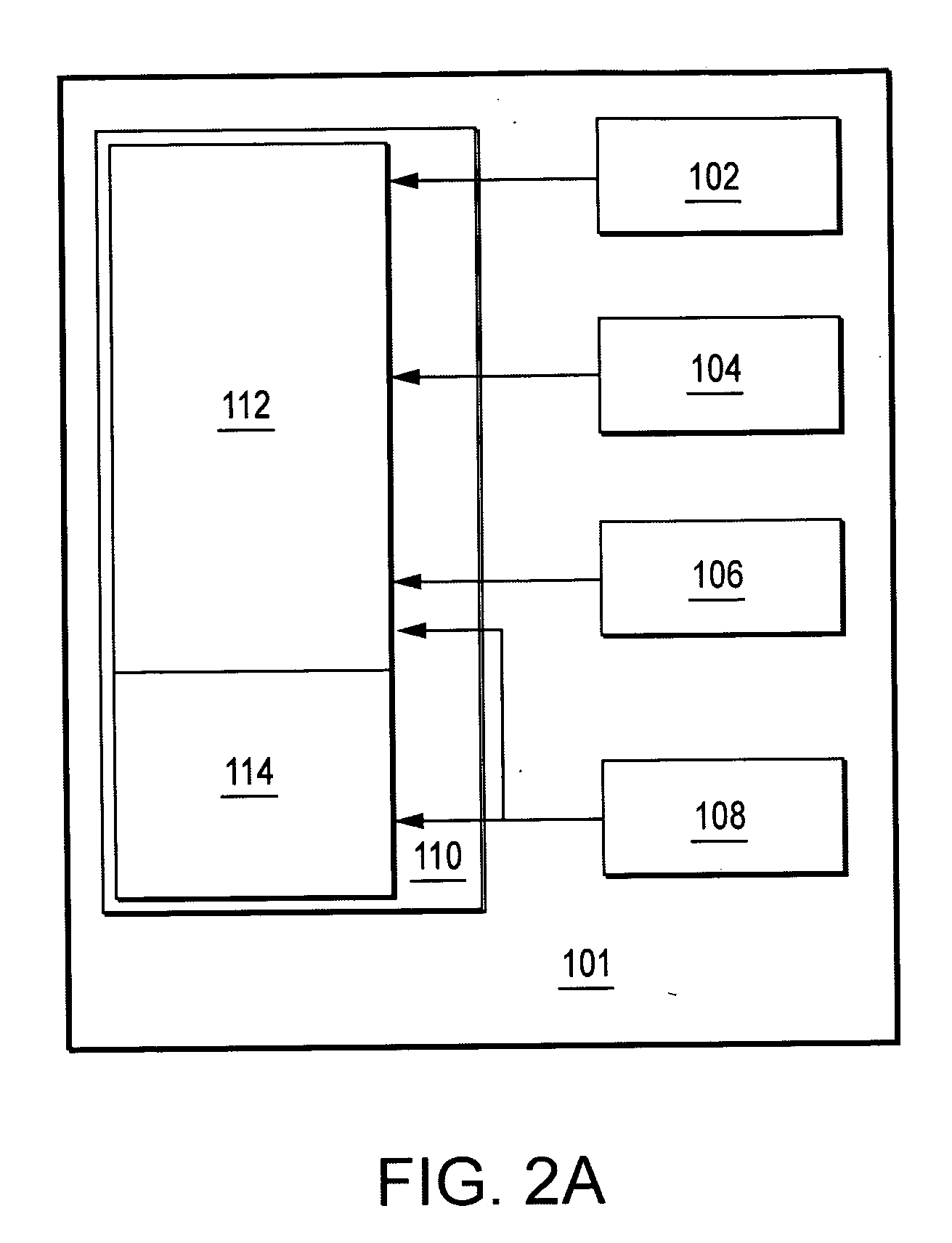
[0029]FIG. 2A illustrates a pulse rate sensor 101 in accordance with the present invention. Emitters 102 (e.g. LED, light emitting diodes) transmit a light source in the near infrared (IR) region into body tissue and a photo detector such as a reflective infra-red sensor 104 that receives the reflected light from the tissue. Pu...


PUM


Abstract

A pulse rate sensor that includes an accelerometer for measuring periodic motion and a piezo sensor for detecting erratic motion is capable of more accurately determining pulse rate by accounting for these types of motion. The pulse rate sensor in accordance with the present invention diminishes pulse rate signal degradation due to erratic motion through a combination of algorithms that control signal boosting, waveform refinement and signal noise suppression.

Description

BACKGROUND OF THE INVENTION [0001] 1. Field of the Invention [0002] The present invention relates generally to the field of signal processing. More specifically, the present invention is related to pulse rate monitors capable of providing accurate measurement and display of a user's pulse rate during times of physical exercise or other activity. [0003] 2. Background of the Related Art [0004] The accurate measurement of an active person's pulse rate at the wrist is complicated due to the artifacts produced by body motion such as when the person is running or otherwise engaging in physical activity or exercise. Therefore, pulse rate monitors presently in the market utilize chest bands that are worn close to the heart to minimize the effect of motion produced by exercise. Artifacts produced by body motion are detected by pulse rate sensors as “noise” that masks the heart rate pulse signal being measured. In order to mitigate the effects of these artifacts, it is necessary to filter out...

Claims


Application Information

Patent Timeline
IPC IPC(8): A61B5/02
CPCA61B5/02438A61B5/7239A61B5/721
Inventor NAZARIAN, RICHARD A.LUCKE, LORI E.ALFINI, SUSAN S.BINA, MARK J.EVANS, DON W. E.HARRIS, PAULGEATZ, MICHAEL W.
Owner INTEL CORP
Why Eureka
Try Eureka