Welding structure for synthetic resin intake manifold

a synthetic resin and intake manifold technology, applied in the field of welding structure for synthetic resin intake manifolds, can solve the problems of inability to treat the protruding welding burr toward the inside, worsening of intake air flow resistance, and inability to smoothly welding the synthetic resin passage structural member to the synthetic resin intake manifold body. , to achieve the effect of reliably managing, inhibiting the protruding welding burr, and preventing the welding burr from protruding

Inactive Publication Date: 2006-04-27
TOYOTA JIDOSHA KK
View PDF8 Cites 12 Cited by
  • Summary
  • Abstract
  • Description
  • Claims
  • Application Information

AI Technical Summary

Benefits of technology

[0011] With this configuration, when the synthetic resin passage structural member is welded to the synthetic resin intake manifold body, the welding protrusion of the second joining flange that is welded to the protrusion of the first joining flange forms welding burr. This welding burr flows to the inside and outside of the joining line and is retained in the inside and outside burr retaining grooves, and, once the inside and outside retaining grooves are full, will then go on to overflow toward the inside and outside. A protrusion timing at which the welding burr overflows from the inside and outside retaining grooves and protrudes toward the inside and outside is different for each side due to the difference in the volumes of the burr retaining grooves. More specifically, the welding burr from the outside burr retaining groove overflows and protrudes to the outside prior to when the welding burr from the inside burr retaining groove overflows and protrudes to the inside. As a result, if welding is stopped when the welding burr protrudes to the outside it is possible to reliably inhibit protrusion of the welding burr to the inside. Thus, it is possible to inhibit formation of a protruding portion to the inside. Accordingly, no protruding portion exists that would act as an obstruction causing worsening of intake air flow resistance. As a result, protrusion of the welding burr to the inside when the inside burr retaining groove becomes full can be reliably inhibited in the same manner as if a protrusion were provided to stop the welding burr when it is going to overflow from the inside burr retaining groove. Further, bulging does not occur at an inside portion of the joining line where the joining flanges are welded together due to the welding burr having no place to escape to at the inside when the welding burr fills the inside burr retaining groove. Thus, welding of the synthetic resin passage structural member to the synthetic resin intake manifold body can be performed smoothly. As a result, protrusion of the welding burr to the inside when the synthetic resin passage structural member is welded to the synthetic resin intake manifold body can be reliably managed using a simple structure.
[0014] With this configuration, when the synthetic resin passage structural member is welded to the synthetic resin intake manifold body, the dimensional difference in the inward-outward direction of the inside and outside burr retaining grooves causes the welding burrs that respectively flow to the inside and outside of the joining line to flow such that: the welding burr in the outside burr retaining groove definitely overflows and protrudes to the outside prior to when the welding burr in the inside burr retaining groove overflows and protrudes to the inside. Accordingly, if welding is stopped when the welding burr protrudes to the outside, it is possible to reliably inhibit protrusion of the welding burr to the inside. Thus, it is possible to inhibit formation of a protruding portion to the inside, and thereby reliably inhibit worsening of intake air flow resistance. As a result, the protrusion of the welding burr to the inside when the synthetic resin passage structural member is welded to the synthetic resin intake manifold body can be reliably managed using a simple structure.
[0017] In fundamental terms, as a result of setting the volume of the inside burr retaining groove to be larger than the volume of the outside burr retaining groove, the welding burr from the outside burr retaining groove overflows and protrudes to the outside prior to when the welding burr from the inside burr retaining groove overflows and protrudes to the inside. Accordingly, if welding is stopped at the protrusion timing when the welding burr protrudes to the outside, protrusion of the welding burr to the inside can be reliably inhibited. Thus, it is possible to reliably inhibit worsening of intake air flow resistance caused by formation of a protruding portion to the inside. Further, it is also possible to reliably inhibit protrusion of the welding burr to the inside while performing welding of the synthetic resin passage forming member to the synthetic resin intake manifold body smoothly. As a result, protrusion of the welding burr to the inside can be reliably managed using a simply structure.

Problems solved by technology

However, there is a possibility that welding burr that overflows form the inside and outside burr retaining grooves will protrude toward both the inside and outside.
However, there is no way to treat the welding burr that protrudes toward the inside.
Accordingly, the protruding portion will form an obstruction that causes worsening of intake air flow resistance.
However, in the technology, there is a possibility that, when the inside burr retaining groove becomes full of welding burr, the welding burr will pass over the extended protrusion and protrude toward the inside.
As a result, there is a possibility that welding of the synthetic resin passage structural member to the synthetic resin intake manifold body will not be performed smoothly and that bulging will occur at an inside portion of the joining line where the joining flanges are welded together.
Accordingly, in the technology, it is not possible to address the problem of the welding burr protruding to the inside when the synthetic resin passage structural member is welded to the synthetic resin intake manifold body.

Method used


Image

  • Welding structure for synthetic resin intake manifold
  • Welding structure for synthetic resin intake manifold
  • Welding structure for synthetic resin intake manifold

Examples


Embodiment Construction

[0026] A preferred embodiment of the invention will be described with reference to the drawings.

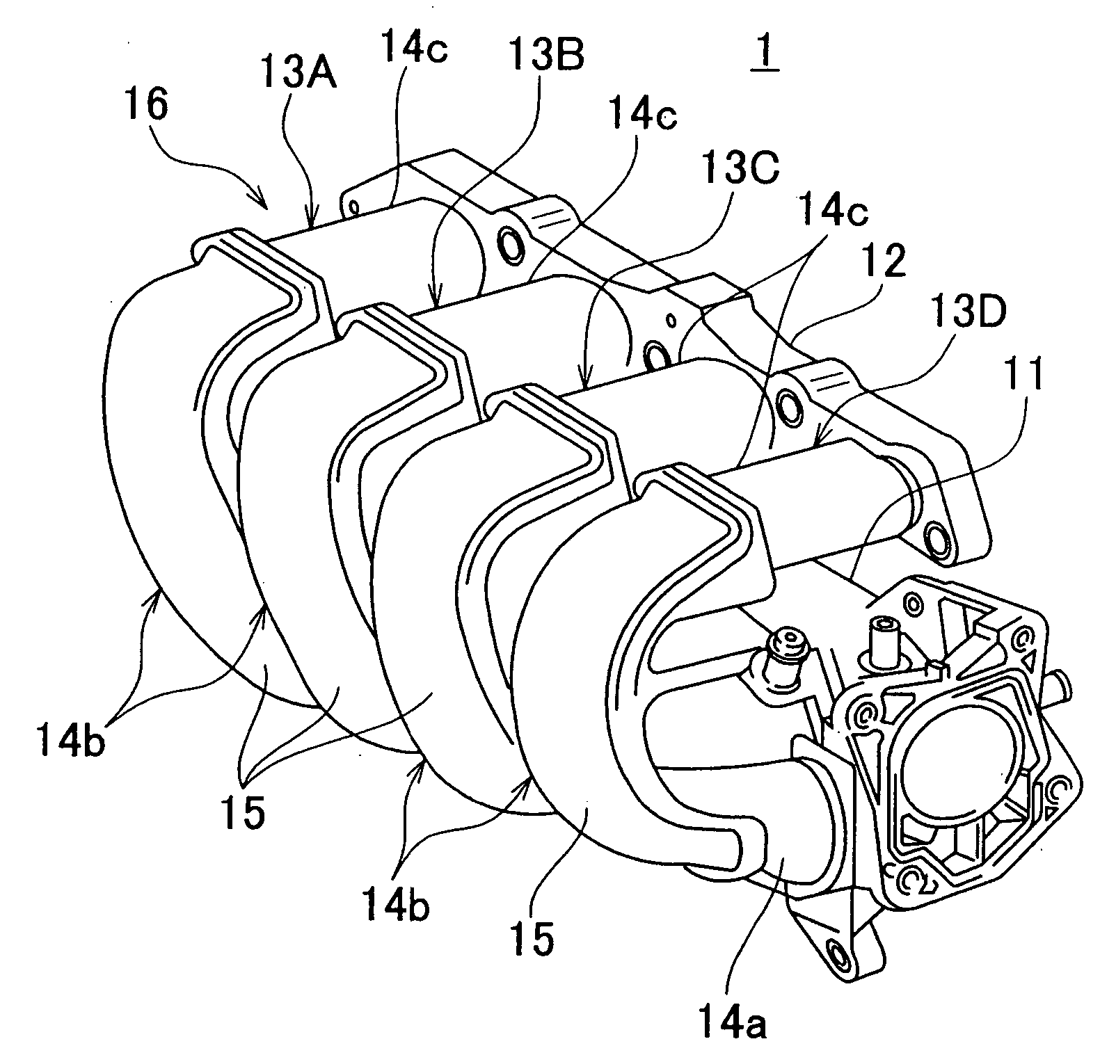
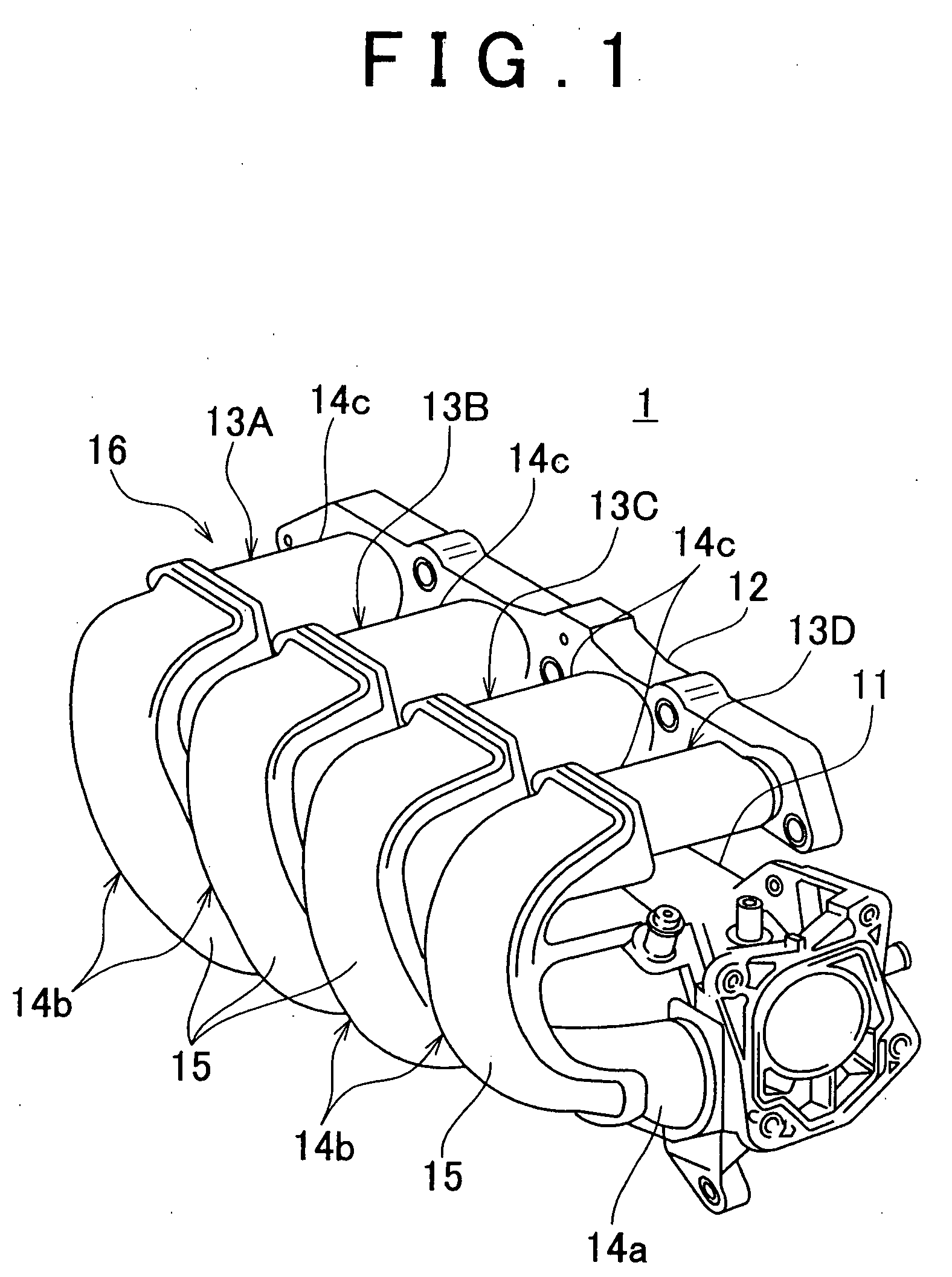
[0027]FIG. 1 a perspective view of a synthetic resin intake manifold 1 that uses a welding structure according to the embodiment of the invention. This synthetic resin intake manifold 1 supplies intake air to an engine (not shown). In this case, an in-line four cylinder engine is employed as the engine. The synthetic resin intake manifold 1 is integrally provided with a surge tank 11 at an upstream side thereof. A downstream side of the synthetic resin intake manifold 1 is attached to the engine using an attachment use flange 12.

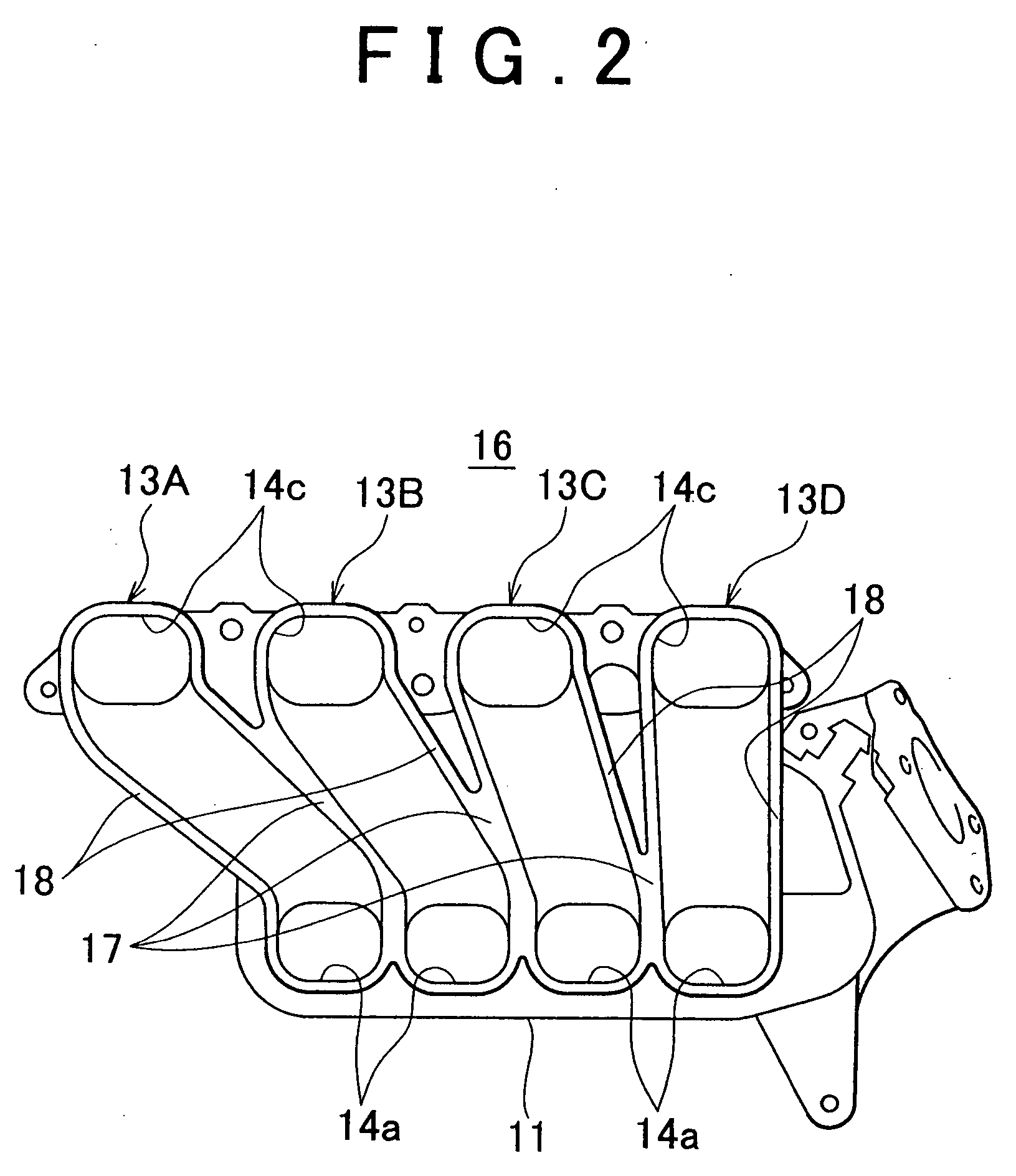
[0028] The synthetic resin intake manifold 1 is formed from thermoplastic resin, and is provided, as shown in FIG. 2, with respective intake passages 13A, 13B, 13C and 13D that correspond to four cylinders, not shown. Each intake passage 13A, 13B, 13C and 13D, as shown in FIG. 1, includes an upstream straight passage portion 14a (only one of these is shown in FI...


PUM

PropertyMeasurementUnit
volumeaaaaaaaaaa
dimensionaaaaaaaaaa
air flow resistanceaaaaaaaaaa

Abstract

A synthetic resin intake manifold body and a synthetic resin passage structural member are respectively provided with a body side joining flange and a structural member side joining flange that are continuously formed along a joining line. A protrusion is provided on the body side joining flange and a welding protrusion and an inside and an outside control wall are provided on the structural member side joining flange. When the synthetic resin passage structural member is positioned and aligned with respect to the synthetic resin intake manifold body along the joining line prior to welding, a volume of an inside burr retaining groove is set to be larger than a volume of an outside burr retaining groove.

Description

INCORPORATION BY REFERENCE [0001] The disclosure of Japanese Patent Application No. 2004-311621 filed on Oct. 27, 2004 including the specification, drawings and abstract is incorporated herein by reference in its entirety. BACKGROUND OF THE INVENTION [0002] 1. Field of the Invention [0003] The invention relates to a welding structure for a synthetic resin intake manifold in which a synthetic resin passage structural member is welded to a synthetic resin intake manifold body along a joining line that has a loop shape. More specifically, the invention relates to an approach that enables welding to be smoothly performed while ensuring that welding burr does not protrude toward an inside of the joining line when welding. [0004] 2. Description of the Related Art [0005] Welding structures for this type of synthetic resin intake manifold are generally known in which a synthetic resin passage structural member that forms at least a portion of a synthetic resin intake manifold is welded alon...

Claims


Application Information

Patent Timeline
Patent Type & Authority Applications(United States)
IPC IPC(8): F02M35/10
CPCB29C65/02B29C65/04B29C65/06B29C65/20B29C66/1312B29C66/322B29C66/54B29C66/972B29K2101/12B29L2031/749B29L2031/7492F02M35/10111F02M35/10321F02M35/1036F02M35/112B29C65/222B29C66/112B29C66/114B29C66/1142B29C66/301
Inventor UEMATSU, SATOSHI
Owner TOYOTA JIDOSHA KK
Why Eureka
Try Eureka