Heat exchanger, heat exchanger tube member, heat exchanger fin member and process for fabricating the heat exchanger

a heat exchanger and fin technology, applied in the field of heat exchanges, can solve the problem of low heat exchange efficiency

Inactive Publication Date: 2006-04-27
SHOWA DENKO KK
View PDF11 Cites 44 Cited by
  • Summary
  • Abstract
  • Description
  • Claims
  • Application Information

AI Technical Summary

Benefits of technology

[0012] With the heat exchanger of the present invention, the heat exchange tubes can of course be prevented from pitting, and the separation of the fin from the heat exchange tube can be suppressed. This permits the heat exchanger to maintain its heat exchange performance over a prolonged period of time.

Problems solved by technology

However, with the heat exchanger disclosed in the above publication, the fillet which undergoes sacrificial corrosion permits the fin to separate from the heat exchange tube, consequently entailing the problem of impairing heat transfer between the tube and the fin to lower the heat exchange efficiency.

Method used


Image

  • Heat exchanger, heat exchanger tube member, heat exchanger fin member and process for fabricating the heat exchanger
  • Heat exchanger, heat exchanger tube member, heat exchanger fin member and process for fabricating the heat exchanger
  • Heat exchanger, heat exchanger tube member, heat exchanger fin member and process for fabricating the heat exchanger

Examples


example 1

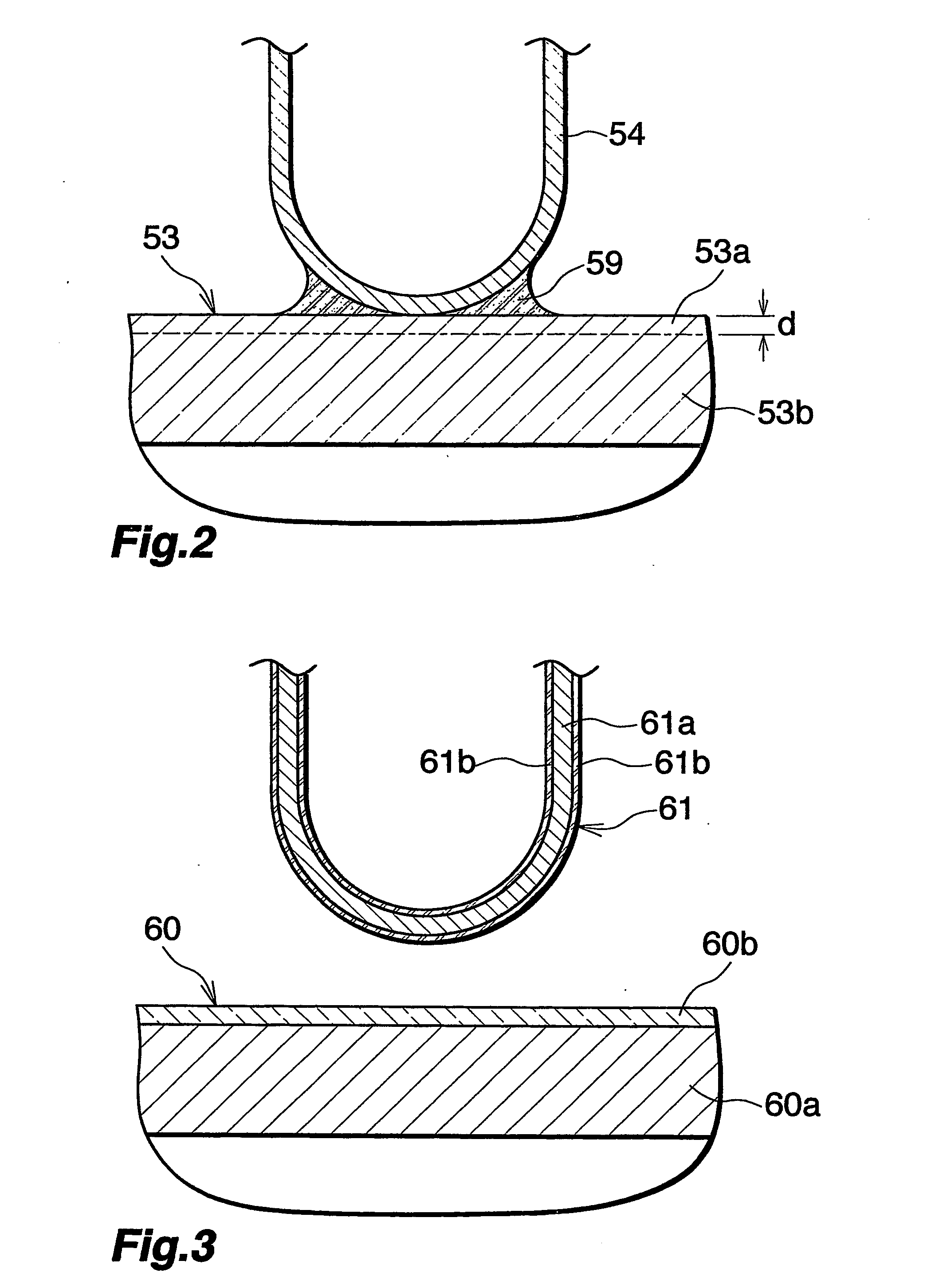
[0056] Refrigerant tube members 60 were produced each by extruding an alloy having the composition shown in Table 1 into a tubular main body 60a and forming a Zn spray layer 60b in an amount of 4 g / m2 over the entire outer peripheral surface of the main body 60a. Also produced were corrugated fin members 61 each comprising a core 61a and a cladding 61b covering each of opposite surfaces of the core 61a, the core and the cladding having the respective compositions shown in Table 2. In the corrugated fin member 61, the cladding ratio of the cladding 61b on one surface of the core 61a was 10%. Also prepared were suitable header members.

TABLE 1Exam-Composition (mass %)pleAlCuMnSiFeMgCrZnTiEx. 1Bal.0.490.290.060.150.010.010.01Comp.Bal.0.150.020.100.210.010.01Ex. 1Comp.Bal.0.400.190.050.170.010.010.010.01Ex. 2

[0057]

TABLE 2Composition (mass %)AlSiFeCuMnMgZnTiExam-CoreBal.0.350.171.21.1ple 1Clad-Bal.8.80.160.30.10.02dingComp.CoreBal.0.350.201.21.2Ex. 1Clad-Bal.8.90.201.2dingComp.CoreBal.0...


PUM

PropertyMeasurementUnit
pHaaaaaaaaaa
depthaaaaaaaaaa
lengthaaaaaaaaaa

Abstract

Suppose each of the refrigerant tubes 53 of a heat exchanger has a potential A at a surface layer portion 53a of an outer periphery thereof and a potential B at a core 53b of the tube 53 other than the surface layer portion 53a thereof, each of the fins 54 has a potential C, and a fillet 59 formed at the brazed portion between the tube 53 and the fin 54 has a potential D. These potentials then have the relationship of A ?C ?D<B. The potential A of the surface layer portion 53a of the outer periphery of the refrigerant tube 53 is −850 to −800 mV, the potential B of the core 53b of the tube 53 is −710 to −670 mV, the potential C of the fin 54 is −850 to −800 mV, and the potential D of the fillet 59 is −850 to −800 mV.

Description

CROSS REFERENCE TO RELATED APPLICATIONS [0001] This application is an application filed under 35 U.S.C. §111(a) claiming the benefit pursuant to 35 U.S.C. §119(e) (1) of the filing data of Provisional Application No. 60 / 428,923 filed Nov. 26, 2002 pursuant to 35 U.S.C. §111(b).TECHNICAL FIELD [0002] The present invention relates to heat exchanges, such as condensers or evaporators for motor vehicle air conditioners for use with a chlorofluorocarbon refrigerant, gas coolers or evaporators for motor vehicle air conditioners for use with a CO2 refrigerant, motor vehicle oil coolers and motor vehicle radiators, heat exchanger tube members, heat exchanger fin members and a process for fabricating the heat exchanger. [0003] The term “potential” as used herein and in the appended claims refers to a potential as measured in a 5 wt. % NaCl aqueous solution having a pH of 3 using a saturated calomel electrode. Of course an atomic symbol representing a metal does not include alloys thereof. BA...

Claims


Application Information

Patent Timeline
Patent Type & Authority Applications(United States)
IPC IPC(8): F28F9/26F28D1/04F25B39/04F25B39/02C23F13/00C23F13/14F28D1/053F28F1/02F28F1/12F28F9/02F28F9/04F28F19/00F28F21/08
CPCB23K1/0012B23K2201/14C23F13/14F25B39/00F28D1/05391F28D2021/0073F28D2021/0085F28F1/022F28F1/128F28F9/0214F28F9/0224F28F9/0246F28F9/0253F28F19/004F28F19/06F28F21/084F28F21/089F28F2220/00F28F2275/04B23K2101/14C23F13/00F28F1/30F28F1/32
Inventor SUDO, TAKASHI
Owner SHOWA DENKO KK
Why Eureka
Try Eureka