
Mounting device for interior equipment in aircraft

Inactive Publication Date: 2006-04-27
AIRBUS OPERATIONS GMBH
View PDF18 Cites 12 Cited by
  • Summary
  • Abstract
  • Description
  • Claims
  • Application Information

AI Technical Summary

Benefits of technology

[0007] The energy absorber, which is integrated in the mounting device, may advantageously limits the mechanical load to the interior equipments, which can for example be an overhead bin in the cabin. For example, the energy absorber may be designed to absorb acceleration energy resulting from the movement of the aircraft. By absorption of acceleration energies the load transmission from the primary structure of the aircraft to the interior equipments, or from the interior equipments to the primary structure of the aircraft may be minimised so that mechanical loads on the various structures are reduced. Advantageously this may result in enhanced passive safety in the cabin. Furthermore, by using the mounting device with an energy absorber, according to the invention, the interior equipments may be designed to save material or weight because the maximum occurring mechanical loads may be reduced.
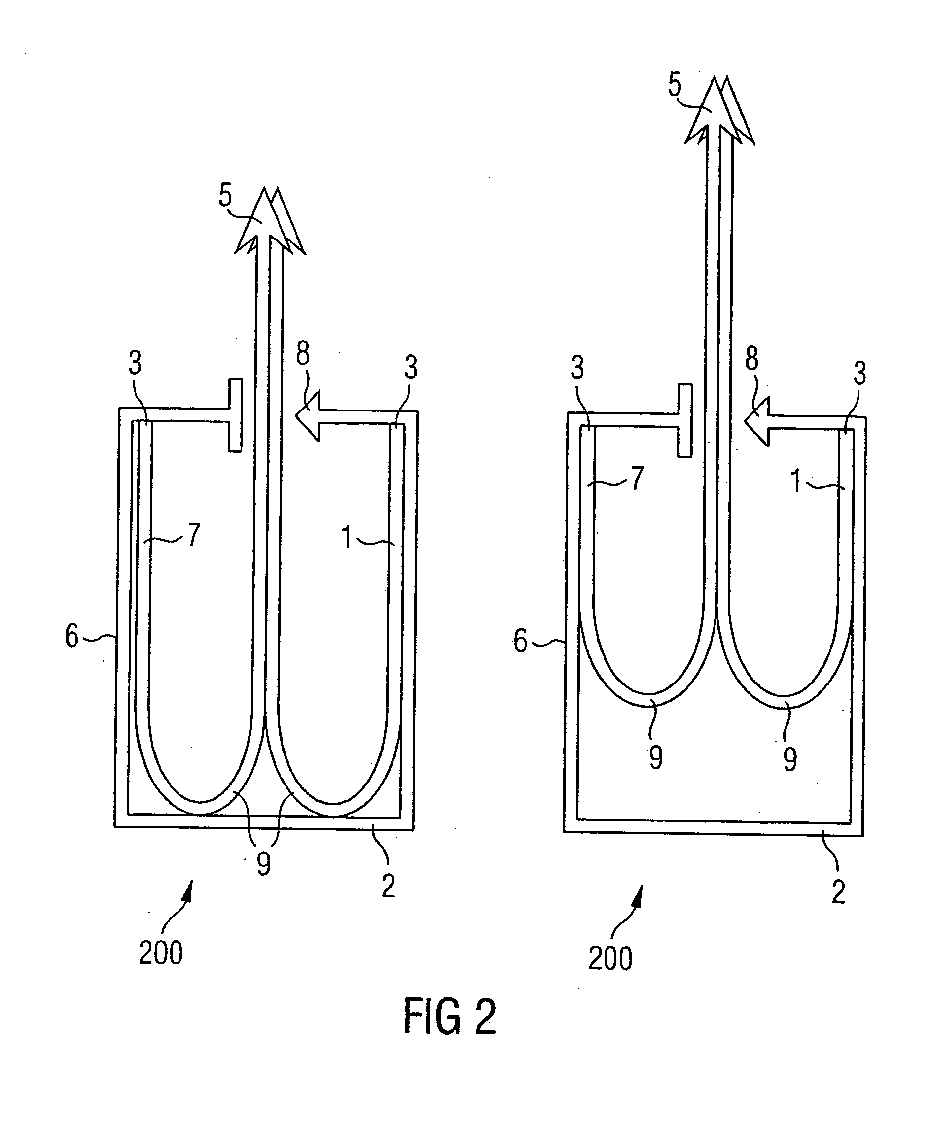
[0023] Advantageously, it may be thus possible to absorb or intercept crash impulses that not only have a component along the guide direction, but also a component perpendicular to the guide direction. In this arrangement the component along the guide direction may be absorbed by the energy absorber of the first mounting device, and the component perpendicular to the guide direction may be absorbed by the energy absorber of the second mounting device. This may make it possible to provide an impulse-specific design of the energy absorbers for individual directions.

Problems solved by technology

In aircraft, mounting devices or fastening elements are used for mounting and fastening interior equipments such as for example ceiling cladding, overhead bins or monuments However, in the case of rigid fastening elements it is often a disadvantage, in particular in the case of strong acceleration, as can occur during severe turbulence or for example also during an emergency landing, that the resulting acceleration forces are directly transferred from the primary structure of the aircraft by way of the mounting device to the fastened interior equipment.
Failure of the mounting, such as can occur for example by its breaking away from the interior equipment as a result of excessive acceleration forces, leads to damage to the mounting, the interior equipments or the primary structure of the aircraft and further can also endanger or injure the passengers or can lead to impediments to any evacuation.

Method used


Image

  • Mounting device for interior equipment in aircraft
  • Mounting device for interior equipment in aircraft
  • Mounting device for interior equipment in aircraft

Examples


Embodiment Construction

[0032] In the following description of the figures, the same reference signs are used for identical or similar elements.

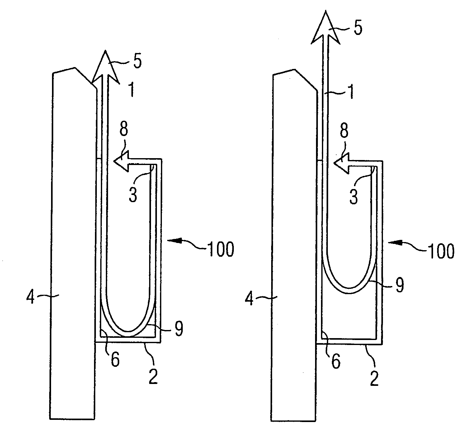
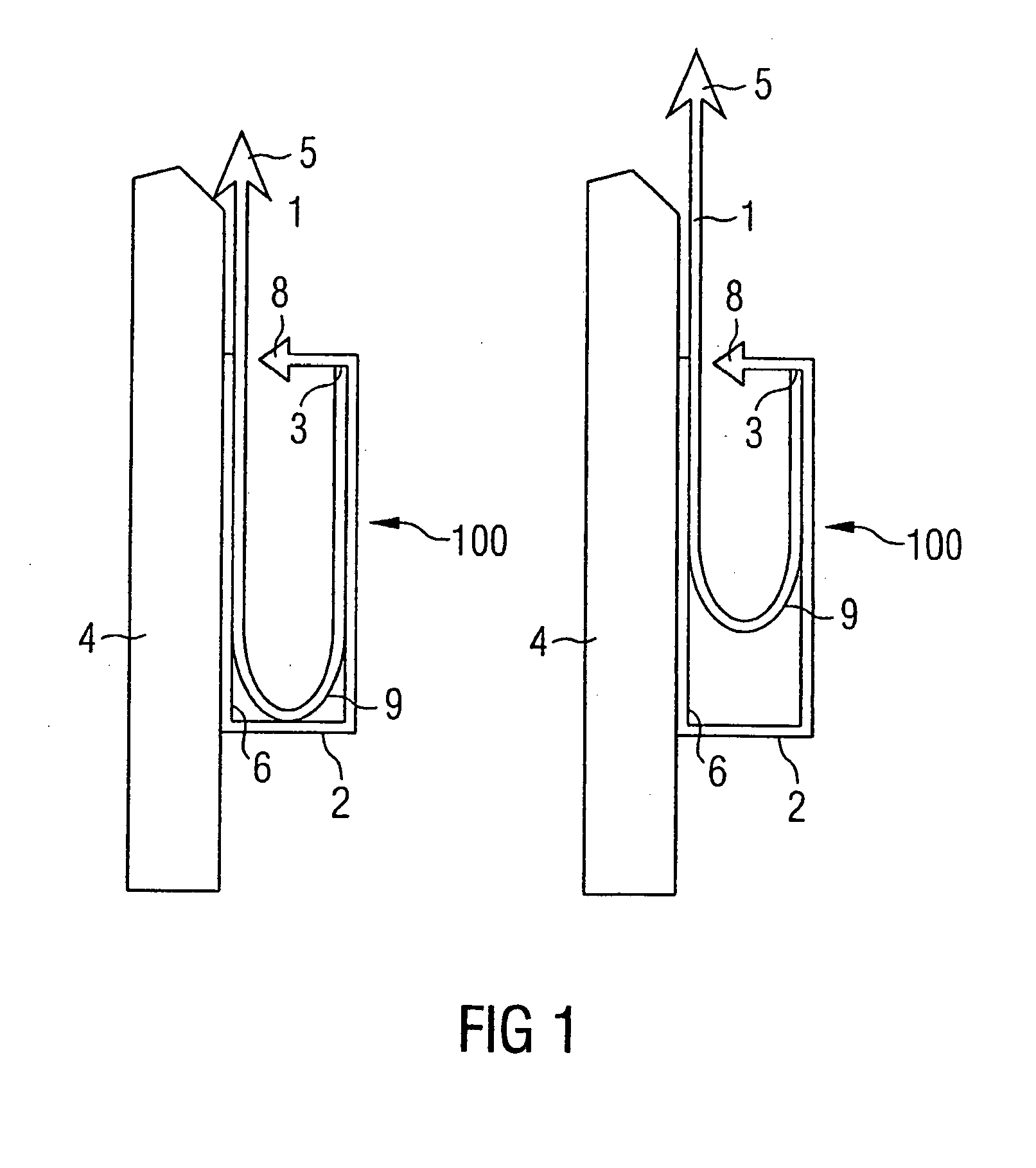
[0033]FIG. 1 shows a diagrammatic view of a mounting device in the initial state and after partial extension according to an embodiment of the present invention. As shown in FIG. 1, the mounting device 100 comprises an energy absorber 1 and a housing 2. The energy absorber 1 is at least partly arranged within the housing 2 and fastened with one of its ends 3 to the inside of the housing. The housing 2 is securely connected to an interior equipment 4, which can for example be a compartment in the cabin which is arranged overhead of the passengers (or vice-versa). This connection takes place for example by means of a screw, a rivet or a self-locking plug-in pin. However, other types of connection, for example gluing or integration in the interior equipment during production, are also imaginable.

[0034] Attaching the mounting device 100 to the interior fitting 4 take...


PUM


Abstract

A mounting device for aircraft comprises an energy absorber and wherein the mounting device is mounted between a primary structure of the aircraft and the interior equipment. In this way the load acting on an interior equipment connected to the primary structure of the aircraft by way of the mounting device can be limited if a crash impulse occurs. The load acting on the primary structure is also limited, which can result in enhanced passive safety for the passengers and in weight reduction.

Description

CROSS-REFERENCE TO RELATED APPLICATIONS [0001] This application claims the benefit of the filing date of U.S. Provisional Patent Application No. 60 / 627,522 filed Nov. 12, 2004, the disclosure of which is hereby incorporated herein by reference.BACKGROUND OF THE INVENTION [0002] The present invention relates to mounting devices or fastening elements for aircraft. In particular the present invention relates to a mounting device for interior equipments or for an interior equipments element of an aircraft, to a mounting system for interior equipment of an aircraft, and to an aircraft comprising a corresponding mounting device. [0003] In aircraft, mounting devices or fastening elements are used for mounting and fastening interior equipments such as for example ceiling cladding, overhead bins or monuments However, in the case of rigid fastening elements it is often a disadvantage, in particular in the case of strong acceleration, as can occur during severe turbulence or for example also d...

Claims


Application Information

Patent Timeline
IPC IPC(8): F16M13/00
CPCB64C1/066B64D9/00B64D11/00B64D11/003F16F7/123Y02T50/46Y02T50/40
Inventor HUMFELDT, DIRKHARRIEHAUSEN, MICHAELSCHROEDER, JANSPERBER, MARTINDEMARY, MICHAEL
Owner AIRBUS OPERATIONS GMBH
Learn More