Eureka AIR delivers breakthrough ideas for toughest innovation challenges, trusted by R&D personnel around the world.

Programmable power supply with dual mode cross over clamps

a programmable power supply and cross-over clamp technology, applied in the direction of electric controllers, instruments, ignition automatic control, etc., can solve the problems of mode cross-over latency and consequently, etc., to reduce the severity of associated overshoots, reduce the mode cross-over latency and consequently, the effect of rapid assumption of control

Active Publication Date: 2006-04-27
KEYSIGHT TECH
View PDF5 Cites 15 Cited by
  • Summary
  • Abstract
  • Description
  • Claims
  • Application Information

AI Technical Summary

Benefits of technology

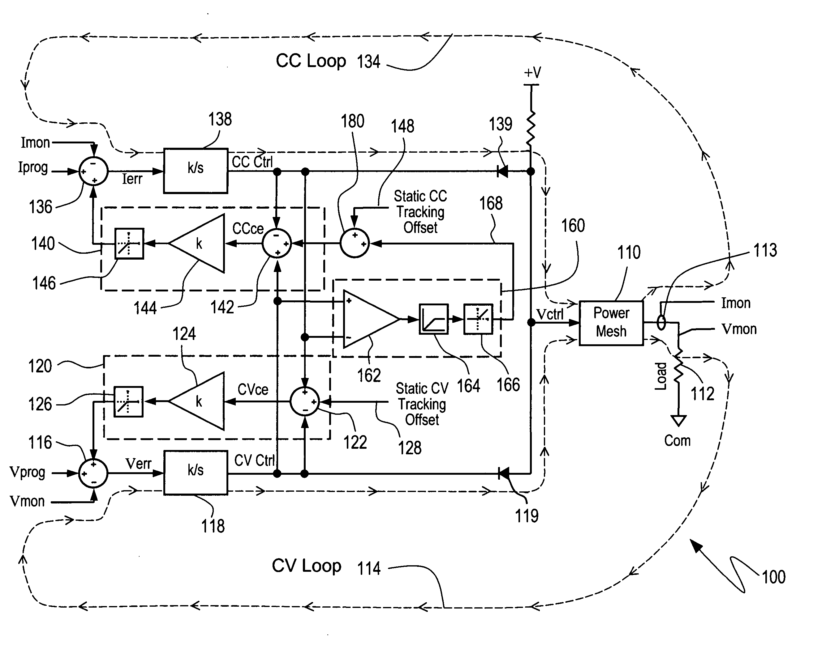
[0005] In the present invention, a pair of clamps, one for the CV loop and one for the CC loop, continually regulate (or clamp) the control voltage of the open loop to be a small, fixed voltage, referred to as a tracking offset, above a voltage of the closed loop, allowing the open loop to rapidly assume control of the power supply should the programmed limit of the open loop be exceeded. The rapid assumption of control dramatically reduces the mode cross-over latency and consequently, the severity of the associated overshoots.
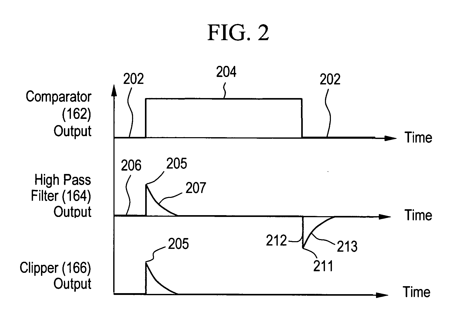
[0006] The present invention addresses the tendency of the tracking clamps to cause the power supply to oscillate. The tendency to oscillate is suppressed by incorporating a circuit that briefly increases the tracking offset of the CC clamp in response to a CV to CC mode transition, temporarily reducing sensitivity of the CC clamp, thereby interrupting any impending oscillation. Alternatively, comparable results are achievable by incorporating a similar circuit in the CV clamp instead of the CC clamp. Briefly increasing the tracking offset allows the use of dual clamps, which results in a programmable power supply with much faster mode cross-over transitions, overshoots that are either substantially reduced or completely eliminated, without generating secondary adverse effects on other aspects of power supply performance, such as for example, stability.

Problems solved by technology

The rapid assumption of control dramatically reduces the mode cross-over latency and consequently, the severity of the associated overshoots.

Method used


Image

  • Programmable power supply with dual mode cross over clamps
  • Programmable power supply with dual mode cross over clamps
  • Programmable power supply with dual mode cross over clamps

Examples


Embodiment Construction

[0017] Reference will now be made in detail to the embodiments of the present invention, examples of which are illustrated in the accompanying drawings, wherein like reference numerals refer to the like elements throughout. The embodiments are described below to explain the present invention by referring to the figures.

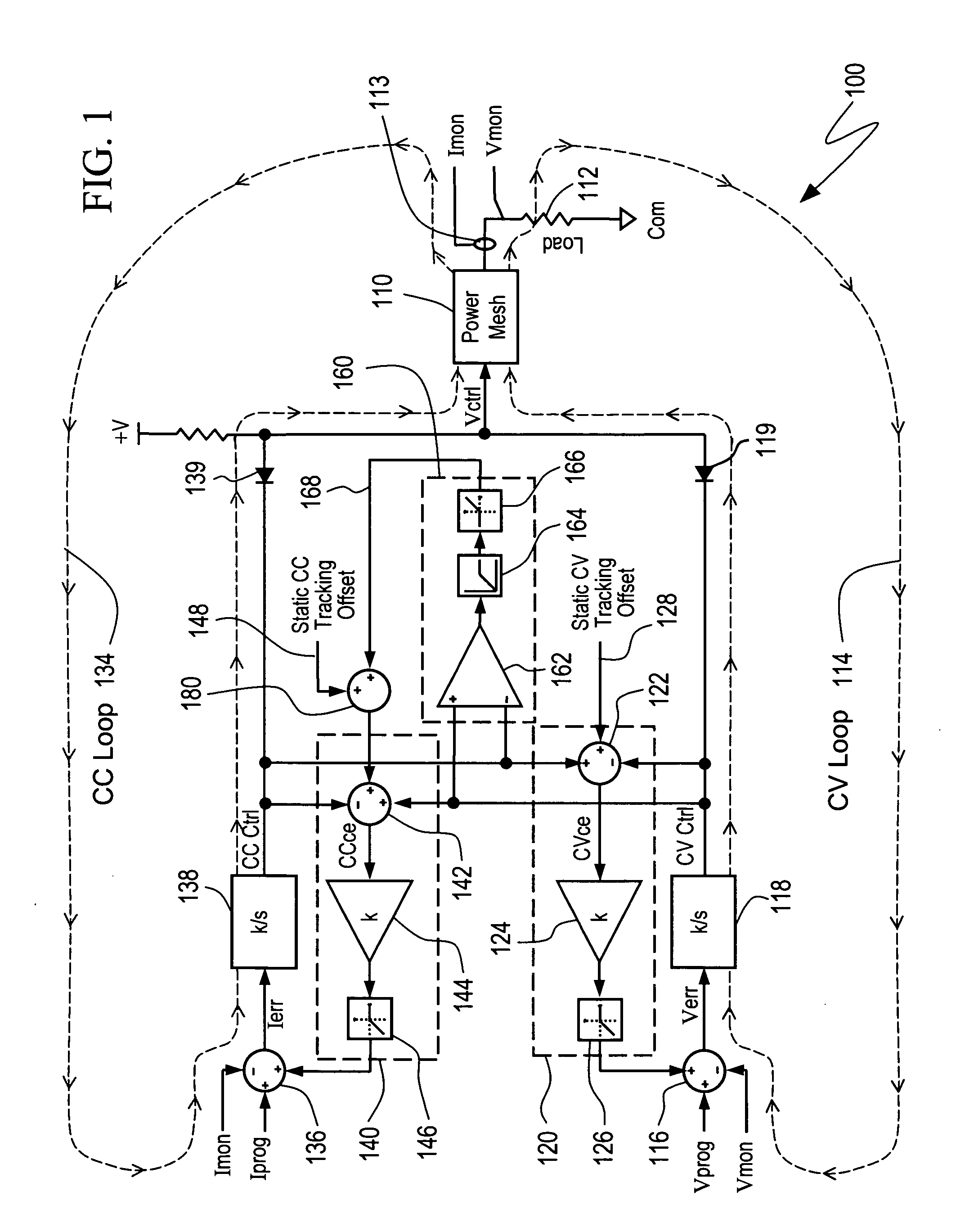
[0018] Referring now to FIG. 1, a power supply 100 according to the present invention comprises a power mesh 110 which drives a user's load 112 in response to a voltage Vctrl to produce a current Imon through the load 112 and a voltage Vmon across the load 112. The voltage Vctrl is selectively controlled by a CV loop 114 and a CC loop 134. The CV loop 114 and the CC loop 134 demand power necessary to regulate voltage and current, respectively, by amplifying an error signal, i.e., differences between user settings, Vprog and Iprog, and actual operating points Vmon and Imon, respectively. An adder 116 provides a difference signal Verr which is amplified by a CV error a...


PUM


Abstract

A power supply programmable for a constant current mode and a constant voltage mode and selectively operable in either mode. Respective circuits associated with each of a constant voltage loop and a constant current loop track a control voltage of the other loop when the other loop is operating closed loop and maintains a control voltage of the open loop at a tracking offset value from the control voltage of the closed loop, allowing the open loop to rapidly assume control of the power supply during a mode transition. The tracking offset value is briefly increased during a mode transition to interrupt oscillation tendencies, resulting in faster mode cross-over and reduced overshoots, while maintaining stability.

Description

CROSS-REFERENCE TO RELATED APPLICATIONS [0001] Not Applicable BACKGROUND OF THE INVENTION [0002] In a programmable DC power supply having a CV mode and a CC mode, modes of operation are implemented with a voltage feedback loop for the CV mode and a current feedback loop for the CC mode, both attempting to regulate their respective parameter to user-specified settings. The DC operating point is determined by a combination of a load line, the large signal voltage-current (V-I) relationship of the load, and either a CV setting or a CC setting, whichever is lower, i.e., whichever setting results in a lower output power level. In the CC and CV modes of operation, the loop that is not regulating opens and relinquishes control to the other loop. Changes in the load may cause the operating point to vary such that the power supply switches modes (CV mode to CC mode or CC mode to CV mode), which is termed mode cross-over. [0003] During a mode cross-over, the loop which was not in control (i.e...

Claims


Application Information

Patent Timeline
IPC IPC(8): H02M7/00
CPCH02M3/137H02M3/156H02M3/33507
Inventor VULOVIC, MARKO
Owner KEYSIGHT TECH
Why Eureka
Eureka Blog
Learn More