Controlling method for image forming apparatus

a control method and image forming technology, applied in the direction of electrographic process apparatus, instruments, computing, etc., can solve the problems of difficult to recognize visually the location of a sheet, take an extra time to select a process function, and difficulty for a novice user to use, so as to reduce the workload

Active Publication Date: 2006-04-27
KONICA MINOLTA BUSINESS TECH INC
View PDF6 Cites 19 Cited by
  • Summary
  • Abstract
  • Description
  • Claims
  • Application Information

AI Technical Summary

Benefits of technology

[0011] An object of the present invention is to provide a controlling method for an image forming apparatus in order to reduce a workload required for selecting and setting various desired process functions.

Problems solved by technology

Therefore, it may be difficult for a novice user who is not familiar with the relation between the setup item for each process function and a corresponding tab to know which tab to be selected in order to reach a proper setup item for a desired process function, and may make take an extra time to select a process function.
However, it is difficult to recognize visually a location on the sheet where a particular process function is to be applied.
Therefore, the user may initiate a process by specifying a wrong location by mistake.
Therefore, it still takes time for setting up the process function and is not solving the abovementioned problem of difficulty in specifying a location on the sheet of printing paper by visually recognizing it.

Method used


Image

  • Controlling method for image forming apparatus
  • Controlling method for image forming apparatus
  • Controlling method for image forming apparatus

Examples


first embodiment

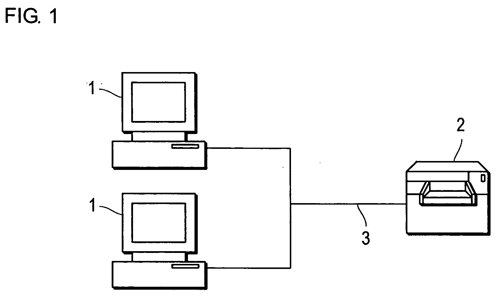
[0049]FIG. 1 is a block diagram showing the entire constitution of an image processing system according to a first embodiment of the present invention.

[0050] The image processing system is equipped with a computer terminal (hereinafter called “PC”) 1 as a printing job transmission apparatus and a printer 2 as an image forming apparatus. The PC 1 and the printer 2 are communicably connected with each other via a network 3. The network 3 can be a LAN connecting computers and network equipment according to standards such as Ethernet®, Token Ring, and FDDI, or a WAN that consists of several LANs connected by a dedicated line.

[0051] The types and the number of equipment to be connected to the network 3 are not limited to those shown in FIG. 1. Also, the PC 1 and the printer 2 can be connected directly (local connection) without recourse to network 3.

[0052] In the present embodiment, a printer driver is installed in the PC 1 as a control program for controlling the printer 2. More spec...

second embodiment

[0142] Although the first embodiment was described as above that the printer driver, which is the control program, is executed by the PC1 in order to process the job, the invention is not limited to it. This invention can be applied for designating locations where selected functions are applied using touch panels in image forming apparatuses of copying machines, compound machines, and MFPs (Multi-Function Peripherals).

[0143] The application to the image forming apparatus will be described below as the second embodiment of the present invention. An MFP will be used in the following description as a typical image forming apparatus.

[0144]FIG. 25 shows the constitution of an MFP 4 as the embodiment of the invention. The MFP 4 includes an MFP main body 70 and a post-processing device (finisher) 80.

[0145] The MFP main body 70 has a CPU 71, a ROM 72, a RAM 73, a hard disk 74, an operating panel unit 75, a printing unit 76, and a network interface 77. These parts are interconnected for e...


PUM


Abstract

A controlling method for controlling an image forming apparatus has a step of displaying a prinnting paper illustration representing printing paper on an operating screen and a step of displaying at least one icon related to a process function of the image forming apparatus. The controlling method further has a step of selecting a process function that corresponds to the specified icon and a step of determining the location to which the selected process function is applied upon receiving an instruction for a position on the printing paper illustration.

Description

[0001] This application is based on Japanese Patent Application Nos. 2004-309999, 2004-310000 and 2004-310001 filed on Oct. 25, 2004, the contents of which are hereby incorporated by reference. BACKGROUND OF THE INVENTION [0002] 1. Field of the Invention [0003] The present invention relates to a controlling method for an image forming apparatus, in particular, a controlling method by using a printer driver. [0004] 2. Description of Related Art [0005] Image forming apparatuses such as printers, copying machines, compound machines and MFPs (Multi-Function Peripherals) have printing, post-processing and various other processing capabilities. A user can select process functions that apply to each printing job by using a control program called printer driver. [0006] A window called “dialog box” is displayed on an operating screen in case of a general printer driver's GUI (graphical user interface). The window has an area where items called “tabs” are displayed. The printer driver disclos...

Claims


Application Information

Patent Timeline
Patent Type & Authority Applications(United States)
IPC IPC(8): G03G15/00
CPCG06F3/1205G06F3/1208G06F3/1264G06F3/1285
Inventor INOUE, AKIRAISHIBASHI, TAKEINAKAGAWA, MICHIHIROENDOU, HIDEKI
Owner KONICA MINOLTA BUSINESS TECH INC
Why Eureka
Try Eureka