Wiper blade

a technology of wiper blades and springs, which is applied in the field of wiper blades, can solve the problems of increasing the number of components of the lever, affecting the durability of the wiper blade, and the inability to distribute the pressing force sufficiently, so as to prevent the plastic deformation of the rod-shaped spring member, improve the durability of the wiper blade, and prevent permanent deformation

Inactive Publication Date: 2006-05-04
MITSUBA CORP
View PDF5 Cites 23 Cited by
  • Summary
  • Abstract
  • Description
  • Claims
  • Application Information

AI Technical Summary

Benefits of technology

[0012] The wiper blade according to the present invention is characterized by comprising: linking strip portions for connecting the deformation restricting blocks to one another, wherein the distance between the adjacent deformation restricting blocks is restricted when excessive bending force is applied to the rubber holder.
[0015] According to the present invention, even if excessive bending force is applied, the plastic deformation of the rod-shaped spring member can be prevented. Therefore, the permanent deformation of the wiper blade can be prevented and the durability of the wiper blade can be improved.

Problems solved by technology

The tournament wiper blade, however, has the problems that components for constituting the lever increase in number and the pressing force cannot be sufficiently distributed because the number of the levers is limited.
Therefore, such a wiper blade may lose its function due to the plastic deformation because the plate spring member exceeds the range of elastic deformation when excessive bending force is applied by for example mishandling.

Method used


Image

  • Wiper blade
  • Wiper blade
  • Wiper blade

Examples


Embodiment Construction

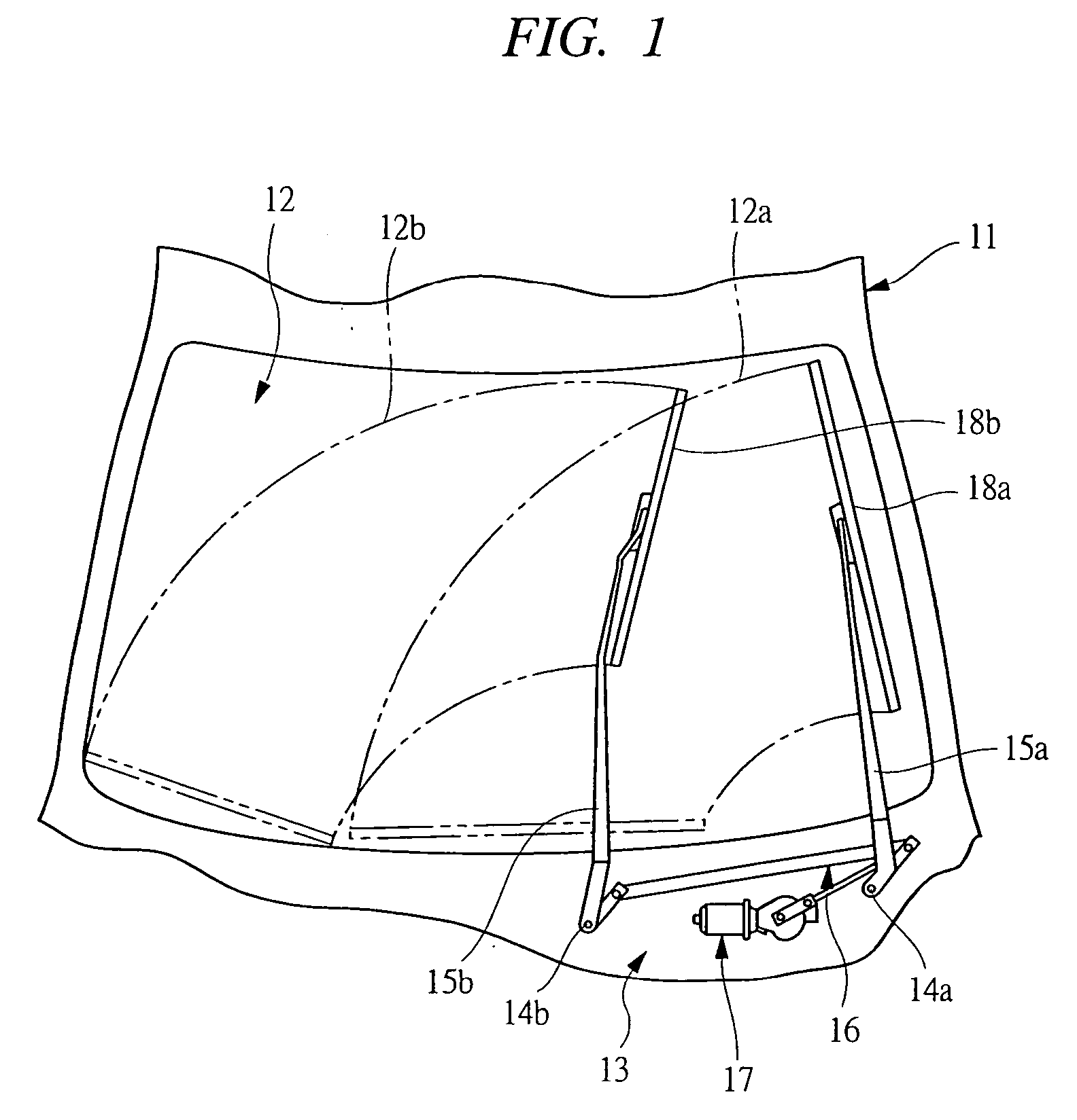
[0029] As shown in FIG. 1, a wiper device 13 is provided on a vehicle 11 to give a driver a good view by wiping raindrops, splashes from a vehicle in from, and others adhering to a windshield 12.

[0030] The wiper device 13 has a wiper arm 15a on the side of a driver's seat or on the DR side, which is swingably provided with respect to the vehicle 11 and fixed to a wiper shaft 14a rotatably supported by the vehicle 11, and similarly, a wiper arm 15b on the side of an assistant driver's seat or on the AS side, which is swingably provided with respect to the vehicle 11 and fixed to a wiper shaft 14b rotatably supported by the vehicle 11. The wiper shafts 14a and 14b are connected to a wiper motor 17 through a link mechanism 16. The rotation of the wiper motor 17 swings the wiper arms 15a and 15b within the range of a given angle.

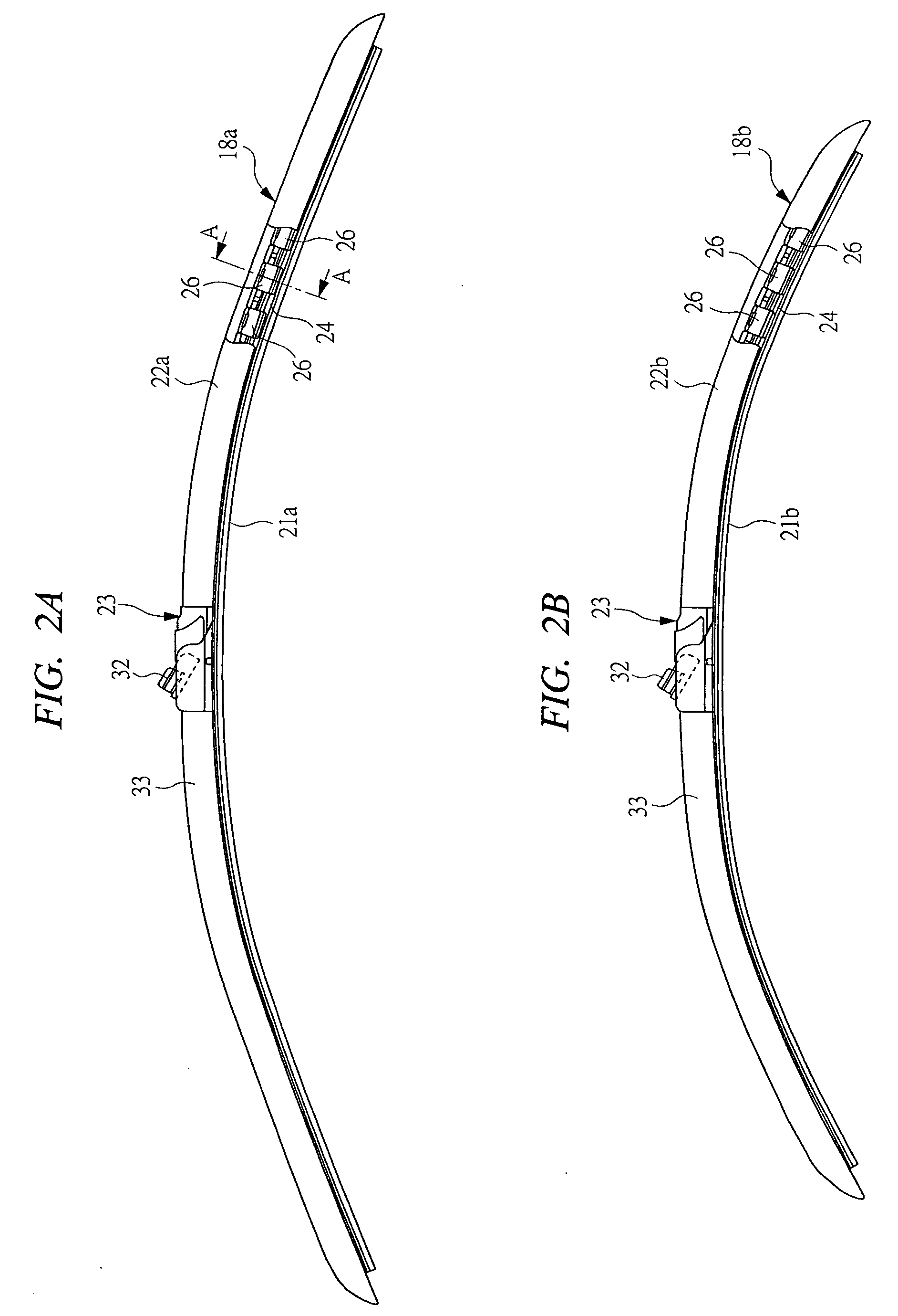
[0031] The wiper blade 18a on the side of a driver's seat or on the DR side is attached to the tip of the wiper arm on the DR side 15a, and the wiper blade 18...


PUM


Abstract

A rubber holder on the DR side (22a) having rod-shaped spring members fixed to holding blocks and a plurality of holding bridges (26) fixed to these rod-shaped members at specified intervals is provided on a wiper blade on the DR side, and a stopper (34) is attached to the rubber holder on the DR side (22a). The stopper (34) has a plurality of deformation restricting blocks (35) disposed between engaging portions (37) formed on the holding bridges (26) and linking strip portions (36) for linking the deformation restricting blocks (35). When excessive bending force is applied to the wiper blade on the DR side, the deformation restricting blocks (35) interfere with the engaging portions (37), or the linking strip portions (36) restrict the increase of the distance between the deformation restricting blocks (35), thereby restricting the deformation of the rubber holder on the DR side (22a) within the range of elastic deformation of the rod-shaped spring members.

Description

CROSS-REFERENCE TO RELATED APPLICATIONS [0001] This application is entitled to the benefit of and incorporates by reference essential subject matter disclosed in International Patent Application No. PCT / JP2003 / 016118 filed on Dec. 16, 2003 and Japanese Patent Application No. 2002-365754 filed on Dec. 17, 2002.TECHNICAL FIELD OF THE INVENTION [0002] The present invention relates to a wiper blade for wiping the surface of a windshield of a vehicle. BACKGROUND OF THE INVENTION [0003] A wiper device is provided on a vehicle such as an automobile to give a driver a good view by wiping off deposits such as raindrops, snow, bugs, and splashes from the car in front. [0004] In general, such a wiper device has a wiper arm swung by an electric motor and a wiper blade fastened to the tip of the wiper arm. The wiper blade is kept pressed against the windshield by a spring mounted inside the wiper arm, and the swing of the wiper arm causes the wiper blade to reciprocate on the surface of the wind...

Claims


Application Information

Patent Timeline
Patent Type & Authority Applications(United States)
IPC IPC(8): B60S1/38
CPCB60S1/38B60S1/381B60S1/3881B60S1/3884B60S2001/3818
Inventor HOSHIO, TAKASHI
Owner MITSUBA CORP
Why Eureka
Try Eureka